

plasma density structure is not easy and the use of multilayer targets, for example, a
foam layer attached with the solid target, is proposed [18], where enhanced energy
coupling from laser to plasmas with use of high contrast laser pulses is demonstrated
with PIC code.
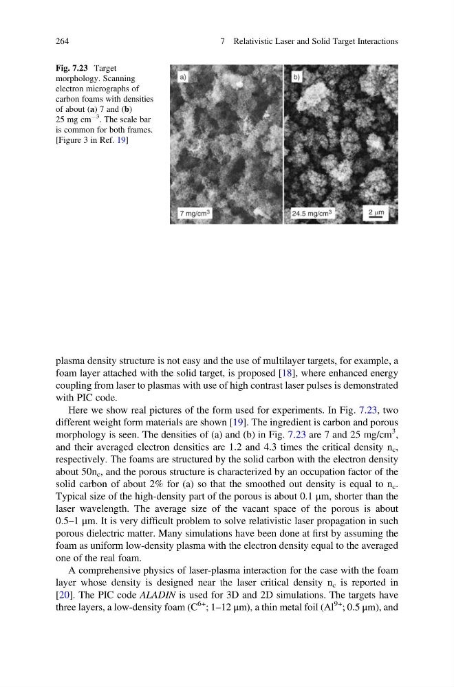
Here we show real pictures of the form used for experiments. In Fig. 7.23, two
different weight form materials are shown [19]. The ingredient is carbon and porous
morphology is seen. The densities of (a) and (b) in Fig. 7.23 are 7 and 25 mg/cm
3 ,
and their averaged electron densities are 1.2 and 4.3 times the critical density n c ,
respectively. The foams are structured by the solid carbon with the electron density
about 50n c , and the porous structure is characterized by an occupation factor of the
solid carbon of about 2% for (a) so that the smoothed out density is equal to n c .
Typical size of the high-density part of the porous is about 0.1 μm, shorter than the
laser wavelength. The average size of the vacant space of the porous is about
0.5–1 μm. It is very difficult problem to solve relativistic laser propagation in such
porous dielectric matter. Many simulations have been done at first by assuming the
foam as uniform low-density plasma with the electron density equal to the averaged
one of the real foam.
A comprehensive physics of laser-plasma interaction for the case with the foam
layer whose density is designed near the laser critical density n c is reported in
[20]. The PIC code ALADIN is used for 3D and 2D simulations. The targets have
three layers, a low-density foam (C
6+ ; 1–12 μm), a thin metal foil (Al
9+ ; 0.5 μm), and
Fig. 7.23 Target
morphology. Scanning
electron micrographs of
carbon foams with densities
of about (a) 7 and (b)
25 mg cm
À3
. The scale bar
is common for both frames.
[Figure 3 in Ref. 19]
264
7 Relativistic Laser and Solid Target Interactions
foam layer attached with the solid target, is proposed [18], where enhanced energy
coupling from laser to plasmas with use of high contrast laser pulses is demonstrated
with PIC code.
Here we show real pictures of the form used for experiments. In Fig. 7.23, two
different weight form materials are shown [19]. The ingredient is carbon and porous
morphology is seen. The densities of (a) and (b) in Fig. 7.23 are 7 and 25 mg/cm
3 ,
and their averaged electron densities are 1.2 and 4.3 times the critical density n c ,
respectively. The foams are structured by the solid carbon with the electron density
about 50n c , and the porous structure is characterized by an occupation factor of the
solid carbon of about 2% for (a) so that the smoothed out density is equal to n c .
Typical size of the high-density part of the porous is about 0.1 μm, shorter than the
laser wavelength. The average size of the vacant space of the porous is about
0.5–1 μm. It is very difficult problem to solve relativistic laser propagation in such
porous dielectric matter. Many simulations have been done at first by assuming the
foam as uniform low-density plasma with the electron density equal to the averaged
one of the real foam.
A comprehensive physics of laser-plasma interaction for the case with the foam
layer whose density is designed near the laser critical density n c is reported in
[20]. The PIC code ALADIN is used for 3D and 2D simulations. The targets have
three layers, a low-density foam (C
6+ ; 1–12 μm), a thin metal foil (Al
9+ ; 0.5 μm), and
Fig. 7.23 Target
morphology. Scanning
electron micrographs of
carbon foams with densities
of about (a) 7 and (b)
25 mg cm
À3
. The scale bar
is common for both frames.
[Figure 3 in Ref. 19]
264
7 Relativistic Laser and Solid Target Interactions