

cometary ions. The asymmetries should be noted. As Rubin et al. (2014c) showed,
solar wind ions are deflected in the opposite direction from cometary pick-up ions
because of the difference in their velocities with respect to the charge-averaged ion
velocity. This results in opposite signs in the Lorentz force term and thus gyration
starts in the opposite direction (cf Fig. 5.8).
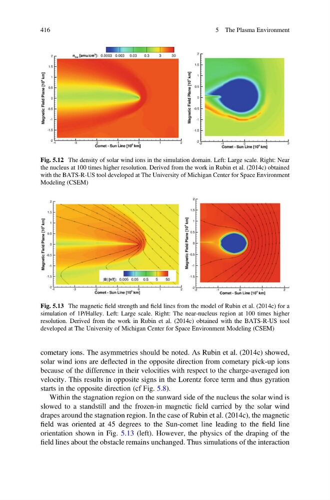
Within the stagnation region on the sunward side of the nucleus the solar wind is
slowed to a standstill and the frozen-in magnetic field carried by the solar wind
drapes around the stagnation region. In the case of Rubin et al. (2014c), the magnetic
field was oriented at 45 degrees to the Sun-comet line leading to the field line
orientation shown in Fig. 5.13 (left). However, the physics of the draping of the
field lines about the obstacle remains unchanged. Thus simulations of the interaction
Fig. 5.12 The density of solar wind ions in the simulation domain. Left: Large scale. Right: Near
the nucleus at 100 times higher resolution. Derived from the work in Rubin et al. (2014c) obtained
with the BATS-R-US tool developed at The University of Michigan Center for Space Environment
Modeling (CSEM)
Fig. 5.13 The magnetic field strength and field lines from the model of Rubin et al. (2014c) for a
simulation of 1P/Halley. Left: Large scale. Right: The near-nucleus region at 100 times higher
resolution. Derived from the work in Rubin et al. (2014c) obtained with the BATS-R-US tool
developed at The University of Michigan Center for Space Environment Modeling (CSEM)
416
5 The Plasma Environment
solar wind ions are deflected in the opposite direction from cometary pick-up ions
because of the difference in their velocities with respect to the charge-averaged ion
velocity. This results in opposite signs in the Lorentz force term and thus gyration
starts in the opposite direction (cf Fig. 5.8).
Within the stagnation region on the sunward side of the nucleus the solar wind is
slowed to a standstill and the frozen-in magnetic field carried by the solar wind
drapes around the stagnation region. In the case of Rubin et al. (2014c), the magnetic
field was oriented at 45 degrees to the Sun-comet line leading to the field line
orientation shown in Fig. 5.13 (left). However, the physics of the draping of the
field lines about the obstacle remains unchanged. Thus simulations of the interaction
Fig. 5.12 The density of solar wind ions in the simulation domain. Left: Large scale. Right: Near
the nucleus at 100 times higher resolution. Derived from the work in Rubin et al. (2014c) obtained
with the BATS-R-US tool developed at The University of Michigan Center for Space Environment
Modeling (CSEM)
Fig. 5.13 The magnetic field strength and field lines from the model of Rubin et al. (2014c) for a
simulation of 1P/Halley. Left: Large scale. Right: The near-nucleus region at 100 times higher
resolution. Derived from the work in Rubin et al. (2014c) obtained with the BATS-R-US tool
developed at The University of Michigan Center for Space Environment Modeling (CSEM)
416
5 The Plasma Environment