

722
D. Froidevaux
Radiation length [X
0 ]
2.5
2
1.5
1
0.5
0
Interaction length [λ]
0.7
0.6
0.4
0.5
0.3
0.1
0.2
0
Services
TRT
SCT
Pixel
Beam-pipe
Services
TRT
SCT
Pixel
Beam-pipe
|η|
0 0.5 1 1.5 2 2.5 3 3.5 4 4.5 5
0 0.5 1 1.5 2 2.5 3 3.5 4 4.5
|η|
5
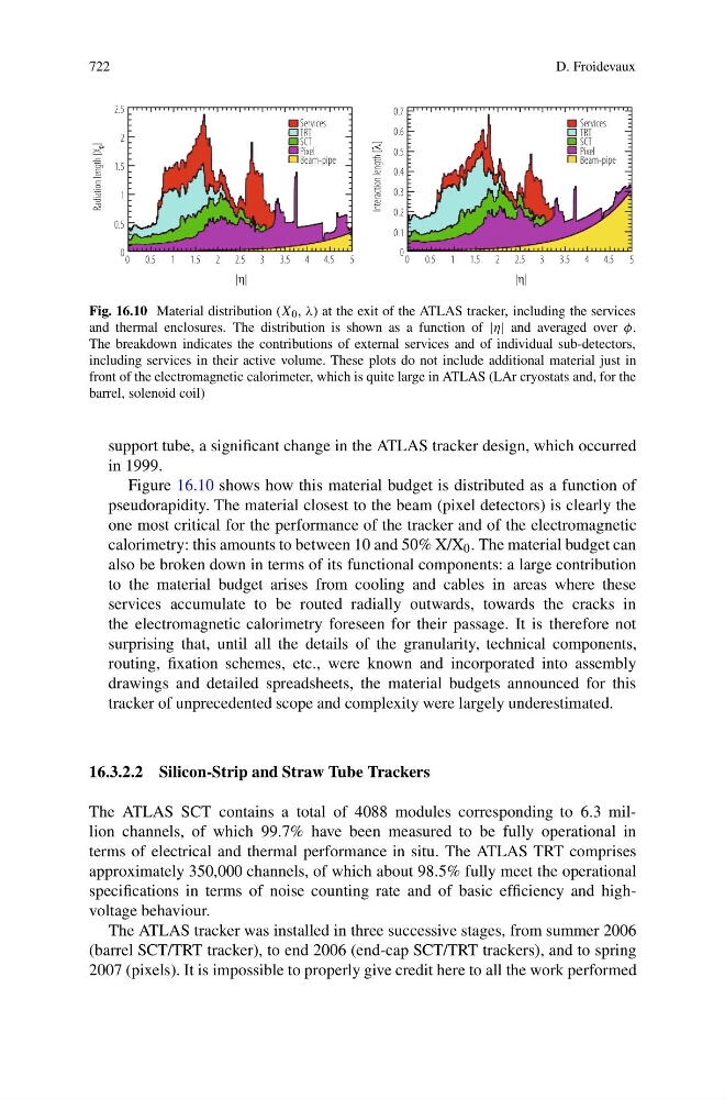
Fig. 16.10 Material distribution (X 0 , λ) at the exit of the ATLAS tracker, including the services
and thermal enclosures. The distribution is shown as a function of |η| and averaged over φ.
The breakdown indicates the contributions of external services and of individual sub-detectors,
including services in their active volume. These plots do not include additional material just in
front of the electromagnetic calorimeter, which is quite large in ATLAS (LAr cryostats and, for the
barrel, solenoid coil)
support tube, a significant change in the ATLAS tracker design, which occurred
in 1999.
Figure 16.10 shows how this material budget is distributed as a function of
pseudorapidity. The material closest to the beam (pixel detectors) is clearly the
one most critical for the performance of the tracker and of the electromagnetic
calorimetry: this amounts to between 10 and 50% X/X 0 . The material budget can
also be broken down in terms of its functional components: a large contribution
to the material budget arises from cooling and cables in areas where these
services accumulate to be routed radially outwards, towards the cracks in
the electromagnetic calorimetry foreseen for their passage. It is therefore not
surprising that, until all the details of the granularity, technical components,
routing, fixation schemes, etc., were known and incorporated into assembly
drawings and detailed spreadsheets, the material budgets announced for this
tracker of unprecedented scope and complexity were largely underestimated.
16.3.2.2 Silicon-Strip and Straw Tube Trackers
The ATLAS SCT contains a total of 4088 modules corresponding to 6.3 million channels, of which 99.7% have been measured to be fully operational in
terms of electrical and thermal performance in situ. The ATLAS TRT comprises
approximately 350,000 channels, of which about 98.5% fully meet the operational
specifications in terms of noise counting rate and of basic efficiency and highvoltage behaviour.
The ATLAS tracker was installed in three successive stages, from summer 2006
(barrel SCT/TRT tracker), to end 2006 (end-cap SCT/TRT trackers), and to spring
2007 (pixels). It is impossible to properly give credit here to all the work performed