

16 Integration of Detectors into a Large Experiment: Examples from ATLAS. . .
721
detector components. The cooling systems themselves are all operating under
severe space limitations on-detector and at high pressure (from 3 to 6 bars). These
systems range from room-temperature monophase C 6 F 14 for the TRT to cold
evaporative C 3 F 8 for the SCT and pixels. Many problems have been encountered
during the commissioning in situ and early operation of these systems, and it is
fair to say a posteriori that this is one area where a stronger and more centralised
engineering effort would have probably come up with a more uniform, more
robust and redundant, and less risky implementation.
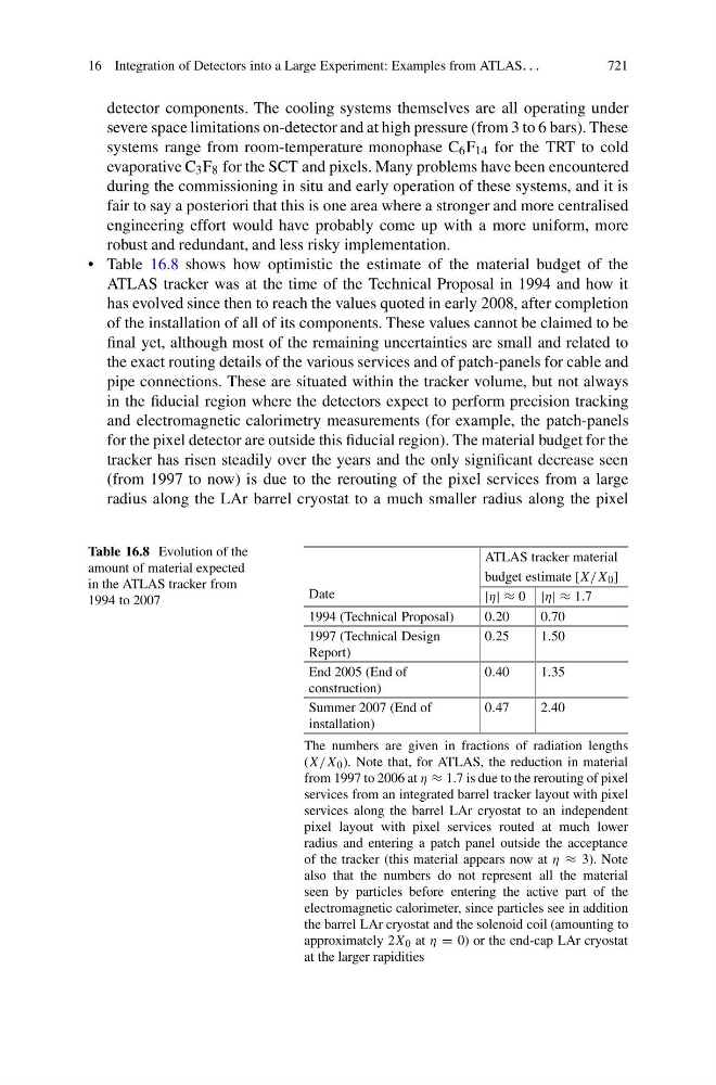
• Table 16.8 shows how optimistic the estimate of the material budget of the
ATLAS tracker was at the time of the Technical Proposal in 1994 and how it
has evolved since then to reach the values quoted in early 2008, after completion
of the installation of all of its components. These values cannot be claimed to be
final yet, although most of the remaining uncertainties are small and related to
the exact routing details of the various services and of patch-panels for cable and
pipe connections. These are situated within the tracker volume, but not always
in the fiducial region where the detectors expect to perform precision tracking
and electromagnetic calorimetry measurements (for example, the patch-panels
for the pixel detector are outside this fiducial region). The material budget for the
tracker has risen steadily over the years and the only significant decrease seen
(from 1997 to now) is due to the rerouting of the pixel services from a large
radius along the LAr barrel cryostat to a much smaller radius along the pixel
Table 16.8 Evolution of the
amount of material expected
in the ATLAS tracker from
1994 to 2007
Date
ATLAS tracker material
budget estimate [X/X 0 ]
|η| ≈ 0 |η| ≈ 1.7
1994 (Technical Proposal)
0.20
0.70
1997 (Technical Design
Report)
0.25
1.50
End 2005 (End of
construction)
0.40
1.35
Summer 2007 (End of
installation)
0.47
2.40
The numbers are given in fractions of radiation lengths
(X/X 0 ). Note that, for ATLAS, the reduction in material
from 1997 to 2006 at η ≈ 1.7 is due to the rerouting of pixel
services from an integrated barrel tracker layout with pixel
services along the barrel LAr cryostat to an independent
pixel layout with pixel services routed at much lower
radius and entering a patch panel outside the acceptance
of the tracker (this material appears now at η ≈ 3). Note
also that the numbers do not represent all the material
seen by particles before entering the active part of the
electromagnetic calorimeter, since particles see in addition
the barrel LAr cryostat and the solenoid coil (amounting to
approximately 2X 0 at η = 0) or the end-cap LAr cryostat
at the larger rapidities