

322
R. Forty and O. Ullaland
0
1
2
3
0.01
0.1
1
10
e
l
g
n
i
s
e
c
a
f
r
u
s
α
π
ω
d
dW
1
p
X
ω
ω
γ ⋅
=
1.6
≈− (
)
7.0
n
l
+
X
d
dW
α
π
ω
(a)
0.0001
0.001
0.01
1
10
100
1000
ω (keV)
Single
surface
N foils
without
absorption
N foils
with
absorption
dW/dω
(b)
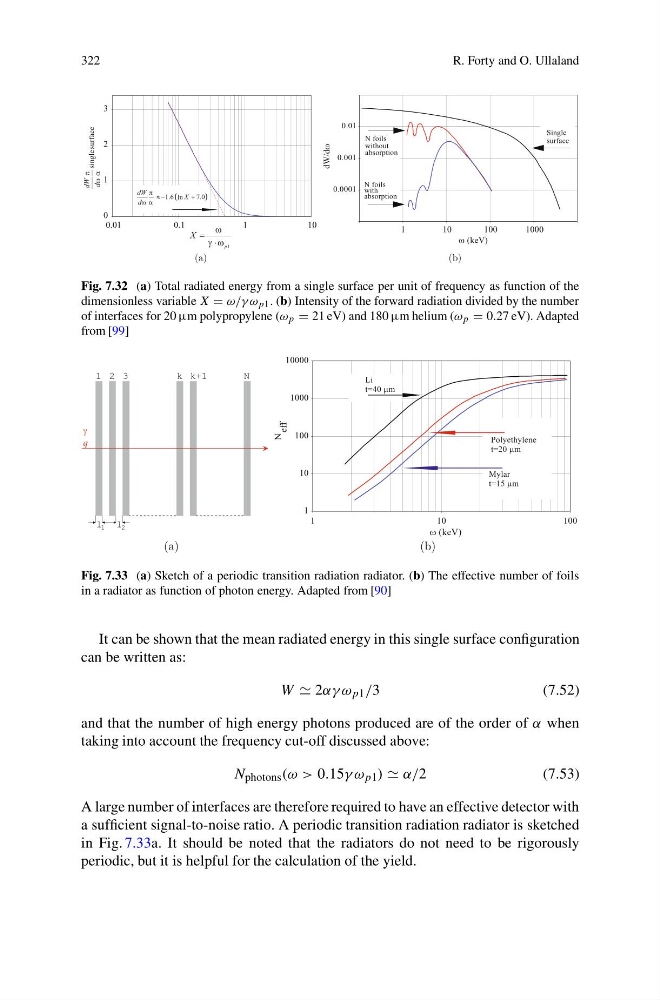
Fig. 7.32 (a) Total radiated energy from a single surface per unit of frequency as function of the
dimensionless variable X = ω/γ ω p1 . (b) Intensity of the forward radiation divided by the number
of interfaces for 20 μm polypropylene (ω p = 21 eV) and 180 μm helium (ω p = 0.27 eV). Adapted
from [99]
N
3
2
1
k k+1
l
l
1
2
γ
q
(a)
1
10
100
1000
10000
1
1 0
1 0 0
ω (keV)
Li
t=40 μm
Polyethylene
t=20 μm
Mylar
t=15 μm
N
eff
(b)
Fig. 7.33 (a) Sketch of a periodic transition radiation radiator. (b) The effective number of foils
in a radiator as function of photon energy. Adapted from [90]
It can be shown that the mean radiated energy in this single surface configuration
can be written as:
W 2αγ ω p1 /3
(7.52)
and that the number of high energy photons produced are of the order of α when
taking into account the frequency cut-off discussed above:
N photons (ω > 0.15γ ω p1 ) α/2
(7.53)
A large number of interfaces are therefore required to have an effective detector with
a sufficient signal-to-noise ratio. A periodic transition radiation radiator is sketched
in Fig. 7.33a. It should be noted that the radiators do not need to be rigorously
periodic, but it is helpful for the calculation of the yield.
R. Forty and O. Ullaland
0
1
2
3
0.01
0.1
1
10
e
l
g
n
i
s
e
c
a
f
r
u
s
α
π
ω
d
dW
1
p
X
ω
ω
γ ⋅
=
1.6
≈− (
)
7.0
n
l
+
X
d
dW
α
π
ω
(a)
0.0001
0.001
0.01
1
10
100
1000
ω (keV)
Single
surface
N foils
without
absorption
N foils
with
absorption
dW/dω
(b)
Fig. 7.32 (a) Total radiated energy from a single surface per unit of frequency as function of the
dimensionless variable X = ω/γ ω p1 . (b) Intensity of the forward radiation divided by the number
of interfaces for 20 μm polypropylene (ω p = 21 eV) and 180 μm helium (ω p = 0.27 eV). Adapted
from [99]
N
3
2
1
k k+1
l
l
1
2
γ
q
(a)
1
10
100
1000
10000
1
1 0
1 0 0
ω (keV)
Li
t=40 μm
Polyethylene
t=20 μm
Mylar
t=15 μm
N
eff
(b)
Fig. 7.33 (a) Sketch of a periodic transition radiation radiator. (b) The effective number of foils
in a radiator as function of photon energy. Adapted from [90]
It can be shown that the mean radiated energy in this single surface configuration
can be written as:
W 2αγ ω p1 /3
(7.52)
and that the number of high energy photons produced are of the order of α when
taking into account the frequency cut-off discussed above:
N photons (ω > 0.15γ ω p1 ) α/2
(7.53)
A large number of interfaces are therefore required to have an effective detector with
a sufficient signal-to-noise ratio. A periodic transition radiation radiator is sketched
in Fig. 7.33a. It should be noted that the radiators do not need to be rigorously
periodic, but it is helpful for the calculation of the yield.