

5 Solid State Detectors
161
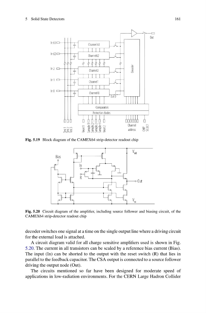
Fig. 5.19 Block diagram of the CAMEX64 strip-detector readout chip
Fig. 5.20 Circuit diagram of the amplifier, including source follower and biasing circuit, of the
CAMEX64 strip-detector readout chip
decoder switches one signal at a time on the single output line where a driving circuit
for the external load is attached.
A circuit diagram valid for all charge sensitive amplifiers used is shown in Fig.
5.20. The current in all transistors can be scaled by a reference bias current (Bias).
The input (In) can be shorted to the output with the reset switch (R) that lies in
parallel to the feedback capacitor. The CSA output is connected to a source follower
driving the output node (Out).
The circuits mentioned so far have been designed for moderate speed of
applications in low-radiation environments. For the CERN Large Hadron Collider
161
Fig. 5.19 Block diagram of the CAMEX64 strip-detector readout chip
Fig. 5.20 Circuit diagram of the amplifier, including source follower and biasing circuit, of the
CAMEX64 strip-detector readout chip
decoder switches one signal at a time on the single output line where a driving circuit
for the external load is attached.
A circuit diagram valid for all charge sensitive amplifiers used is shown in Fig.
5.20. The current in all transistors can be scaled by a reference bias current (Bias).
The input (In) can be shorted to the output with the reset switch (R) that lies in
parallel to the feedback capacitor. The CSA output is connected to a source follower
driving the output node (Out).
The circuits mentioned so far have been designed for moderate speed of
applications in low-radiation environments. For the CERN Large Hadron Collider