

4 Gaseous Detectors
125
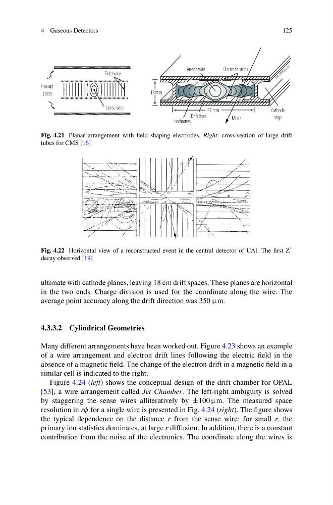
Fig. 4.21 Planar arrangement with field shaping electrodes. Right: cross-section of large drift
tubes for CMS [16]
Fig. 4.22 Horizontal view of a reconstructed event in the central detector of UAl. The first Z
◦
decay observed [19]
ultimate with cathode planes, leaving 18 cm drift spaces. These planes are horizontal
in the two ends. Charge division is used for the coordinate along the wire. The
average point accuracy along the drift direction was 350 μm.
4.3.3.2 Cylindrical Geometries
Many different arrangements have been worked out. Figure 4.23 shows an example
of a wire arrangement and electron drift lines following the electric field in the
absence of a magnetic field. The change of the electron drift in a magnetic field in a
similar cell is indicated to the right.
Figure 4.24 (left) shows the conceptual design of the drift chamber for OPAL
[53], a wire arrangement called Jet Chamber. The left-right ambiguity is solved
by staggering the sense wires alliteratively by ±100 μm. The measured space
resolution in rφ for a single wire is presented in Fig. 4.24 (right). The figure shows
the typical dependence on the distance r from the sense wire: for small r, the
primary ion statistics dominates, at large r diffusion. In addition, there is a constant
contribution from the noise of the electronics. The coordinate along the wires is
125
Fig. 4.21 Planar arrangement with field shaping electrodes. Right: cross-section of large drift
tubes for CMS [16]
Fig. 4.22 Horizontal view of a reconstructed event in the central detector of UAl. The first Z
◦
decay observed [19]
ultimate with cathode planes, leaving 18 cm drift spaces. These planes are horizontal
in the two ends. Charge division is used for the coordinate along the wire. The
average point accuracy along the drift direction was 350 μm.
4.3.3.2 Cylindrical Geometries
Many different arrangements have been worked out. Figure 4.23 shows an example
of a wire arrangement and electron drift lines following the electric field in the
absence of a magnetic field. The change of the electron drift in a magnetic field in a
similar cell is indicated to the right.
Figure 4.24 (left) shows the conceptual design of the drift chamber for OPAL
[53], a wire arrangement called Jet Chamber. The left-right ambiguity is solved
by staggering the sense wires alliteratively by ±100 μm. The measured space
resolution in rφ for a single wire is presented in Fig. 4.24 (right). The figure shows
the typical dependence on the distance r from the sense wire: for small r, the
primary ion statistics dominates, at large r diffusion. In addition, there is a constant
contribution from the noise of the electronics. The coordinate along the wires is