

650
K. Hübner et al.
injection kicker consists of four modules and is located between the Q5 and Q4
quadrupole magnets on the right-hand side of the IP. In order to protect the cold
elements in case of injection failure a large absorber (TDI) is placed 15 m in
front of the D1 separation/recombination dipole magnet right from the IP. The
TDI is complemented by an additional shielding element between the TDI and
D1 magnet (placed 3 m in front of D1) (TCDD) and by two additional collimators
placed on the transition of the matching section left from the IP to the next DS
section.
In order to provide sufficient space for the spectrometer magnet of the LHCb
experiment, IP8 is shifted by 15 half RF wavelengths (3.5 times the nominal bunch
spacing ~11.25 m) towards IR7. This shift of the IP has to be recuperated before
the beam returns to the dispersion suppressor sections and implies a non-symmetric
magnet layout in the matching section.
10.6.2.7 LSS3 and LSS7
The insertion IR3 houses the momentum cleaning systems of both beams, while
IR7 houses the betatron cleaning systems of both beams. Particles with a large
momentum offset are scattered by the primary jaw of IR3. Particles with a large H, V
or combined H-V betatron amplitudes are scattered by the primary collimator jaws
in IR7. In both cases the scattered particles are absorbed by secondary collimators.
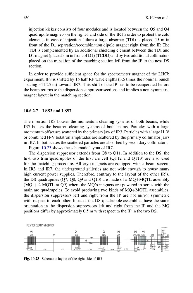
Figure 10.23 shows the schematic layout of IR7.
The dispersion suppressor extends from Q8 to Q11. In addition to the DS, the
first two trim quadrupoles of the first arc cell (QT12 and QT13) are also used
for the matching procedure. All cryo-magnets are equipped with a beam screen.
In IR3 and IR7, the underground galleries are not wide enough to house many
high current power supplies. Therefore, contrary to the layout of the other IR’s,
the DS quadrupoles (Q7, Q8, Q9 and Q10) are made of a MQ+MQTL assembly
(MQ + 2 MQTL at Q9) where the MQ’s magnets are powered in series with the
main arc quadrupoles. To avoid producing two kinds of MQ+MQTL assemblies,
the dispersion suppressors left and right from the IP are not mirror symmetric
with respect to each other. Instead, the DS quadrupole assemblies have the same
orientation in the dispersion suppressors left and right from the IP and the MQ
positions differ by approximately 0.5 m with respect to the IP in the two DS.
Fig. 10.23 Schematic layout of the right side of IR7