

10 The Largest Accelerators and Colliders of Their Time
649
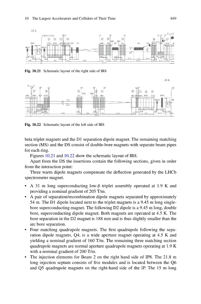
Fig. 10.21 Schematic layout of the right side of IR8
Fig. 10.22 Schematic layout of the left side of IR8
beta triplet magnets and the D1 separation dipole magnet. The remaining matching
section (MS) and the DS consist of double-bore magnets with separate beam pipes
for each ring.
Figures 10.21 and 10.22 show the schematic layout of IR8.
Apart from the DS the insertions contain the following sections, given in order
from the interaction point:
Three warm dipole magnets compensate the deflection generated by the LHCb
spectrometer magnet.
• A 31 m long superconducting low-β triplet assembly operated at 1.9 K and
providing a nominal gradient of 205 T/m.
• A pair of separation/recombination dipole magnets separated by approximately
54 m. The D1 dipole located next to the triplet magnets is a 9.45 m long singlebore superconducting magnet. The following D2 dipole is a 9.45 m long, double
bore, superconducting dipole magnet. Both magnets are operated at 4.5 K. The
bore separation in the D2 magnet is 188 mm and is thus slightly smaller than the
arc bore separation.
• Four matching quadrupole magnets. The first quadrupole following the separation dipole magnets, Q4, is a wide aperture magnet operating at 4.5 K and
yielding a nominal gradient of 160 T/m. The remaining three matching section
quadrupole magnets are normal aperture quadrupole magnets operating at 1.9 K
with a nominal gradient of 200 T/m.
• The injection elements for Beam 2 on the right hand side of IP8. The 21.8 m
long injection septum consists of five modules and is located between the Q6
and Q5 quadrupole magnets on the right-hand side of the IP. The 15 m long