

562
M. Lamont et al.
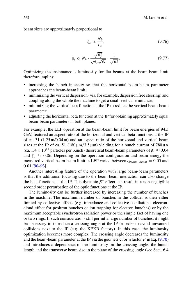
beam sizes are approximately proportional to
ξ x ∝
N b
x
,
(9.76)
ξ y ∝ N b ·
β ∗
y
√
y
√
x
·
1
β ∗
x
.
(9.77)
Optimizing the instantaneous luminosity for flat beams at the beam-beam limit
therefore implies:
• increasing the bunch intensity so that the horizontal beam-beam parameter
approaches the beam-beam limit;
• minimizing the vertical dispersion (via, for example, dispersion free steering) and
coupling along the whole the machine to get a small vertical emittance;
• minimizing the vertical beta function at the IP to reduce the vertical beam-beam
parameter;
• adjusting the horizontal beta function at the IP for obtaining approximately equal
beam-beam parameters in both planes.
For example, the LEP operation at the beam-beam limit for beam energies of 94.5
GeV, featured an aspect ratio of the horizontal and vertical beta functions at the IP
of ca. 31 (1.25 m/0.04 m) and an aspect ratio of the horizontal and vertical beam
sizes at the IP of ca. 51 (180 μm/3.5 μm) yielding for a bunch current of 780 μA
(ca. 1.4 × 10 11 particles per bunch) theoretical beam-beam parameters of ξ x ≈ 0.04
and ξ y ≈ 0.06. Depending on the operation configuration and beam energy the
measured vertical beam-beam limit in LEP varied between ξ beam−beam = 0.05 and
0.01 [90–93].
Another interesting feature of the operation with large beam-beam parameters
is that the additional focusing due to the beam-beam interaction can also change
the beta-functions at the IP. This dynamic β ∗ effect can result in a non-negligible
second order perturbation of the optic functions at the IP.
The luminosity can be further increased by increasing the number of bunches
in the machine. The maximum number of bunches in the collider is then either
limited by collective effects (e.g. impedance and collective oscillations, electroncloud effect for positron bunches or ion trapping for electron bunches) or by the
maximum acceptable synchrotron radiation power or the simple fact of having one
or two rings. If such considerations still permit a large number of bunches, it might
be necessary to introduce a crossing angle at the IP in order to avoid unwanted
collisions next to the IP (e.g. the KEKB factory). In this case, the luminosity
optimization becomes more complex. The crossing angle decreases the luminosity
and the beam-beam parameter at the IP via the geometric form factor F in Eq. (9.70)
and introduces a dependence of the luminosity on the crossing angle, the bunch
length and the transverse beam size in the plane of the crossing angle (see Sect. 6.4
M. Lamont et al.
beam sizes are approximately proportional to
ξ x ∝
N b
x
,
(9.76)
ξ y ∝ N b ·
β ∗
y
√
y
√
x
·
1
β ∗
x
.
(9.77)
Optimizing the instantaneous luminosity for flat beams at the beam-beam limit
therefore implies:
• increasing the bunch intensity so that the horizontal beam-beam parameter
approaches the beam-beam limit;
• minimizing the vertical dispersion (via, for example, dispersion free steering) and
coupling along the whole the machine to get a small vertical emittance;
• minimizing the vertical beta function at the IP to reduce the vertical beam-beam
parameter;
• adjusting the horizontal beta function at the IP for obtaining approximately equal
beam-beam parameters in both planes.
For example, the LEP operation at the beam-beam limit for beam energies of 94.5
GeV, featured an aspect ratio of the horizontal and vertical beta functions at the IP
of ca. 31 (1.25 m/0.04 m) and an aspect ratio of the horizontal and vertical beam
sizes at the IP of ca. 51 (180 μm/3.5 μm) yielding for a bunch current of 780 μA
(ca. 1.4 × 10 11 particles per bunch) theoretical beam-beam parameters of ξ x ≈ 0.04
and ξ y ≈ 0.06. Depending on the operation configuration and beam energy the
measured vertical beam-beam limit in LEP varied between ξ beam−beam = 0.05 and
0.01 [90–93].
Another interesting feature of the operation with large beam-beam parameters
is that the additional focusing due to the beam-beam interaction can also change
the beta-functions at the IP. This dynamic β ∗ effect can result in a non-negligible
second order perturbation of the optic functions at the IP.
The luminosity can be further increased by increasing the number of bunches
in the machine. The maximum number of bunches in the collider is then either
limited by collective effects (e.g. impedance and collective oscillations, electroncloud effect for positron bunches or ion trapping for electron bunches) or by the
maximum acceptable synchrotron radiation power or the simple fact of having one
or two rings. If such considerations still permit a large number of bunches, it might
be necessary to introduce a crossing angle at the IP in order to avoid unwanted
collisions next to the IP (e.g. the KEKB factory). In this case, the luminosity
optimization becomes more complex. The crossing angle decreases the luminosity
and the beam-beam parameter at the IP via the geometric form factor F in Eq. (9.70)
and introduces a dependence of the luminosity on the crossing angle, the bunch
length and the transverse beam size in the plane of the crossing angle (see Sect. 6.4