

9 Accelerator Operations
535
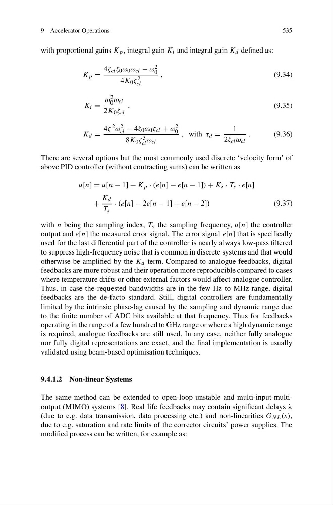
with proportional gains K p , integral gain K i and integral gain K d defined as:
K p =
4ζ cl ζ 0 ω 0 ω cl − ω 2
0
4K 0 ζ 2
cl
,
(9.34)
K i =
ω 2
0 ω cl
2K 0 ζ cl
,
(9.35)
K d =
4ζ 2 ω 2
cl − 4ζ 0 ω 0 ζ cl + ω 2
0
8K 0 ζ 3
cl ω cl
, with τ d =
1
2ζ cl ω cl
.
(9.36)
There are several options but the most commonly used discrete ‘velocity form’ of
above PID controller (without contracting sums) can be written as
u[n] = u[n − 1] + K p · (e[n] − e[n − 1]) + K i · T s · e[n]
+
K d
T s
· (e[n] − 2e[n − 1] + e[n − 2])
(9.37)
with n being the sampling index, T s the sampling frequency, u[n] the controller
output and e[n] the measured error signal. The error signal e[n] that is specifically
used for the last differential part of the controller is nearly always low-pass filtered
to suppress high-frequency noise that is common in discrete systems and that would
otherwise be amplified by the K d term. Compared to analogue feedbacks, digital
feedbacks are more robust and their operation more reproducible compared to cases
where temperature drifts or other external factors would affect analogue controller.
Thus, in case the requested bandwidths are in the few Hz to MHz-range, digital
feedbacks are the de-facto standard. Still, digital controllers are fundamentally
limited by the intrinsic phase-lag caused by the sampling and dynamic range due
to the finite number of ADC bits available at that frequency. Thus for feedbacks
operating in the range of a few hundred to GHz range or where a high dynamic range
is required, analogue feedbacks are still used. In any case, neither fully analogue
nor fully digital representations are exact, and the final implementation is usually
validated using beam-based optimisation techniques.
9.4.1.2 Non-linear Systems
The same method can be extended to open-loop unstable and multi-input-multioutput (MIMO) systems [8]. Real life feedbacks may contain significant delays λ
(due to e.g. data transmission, data processing etc.) and non-linearities G NL (s),
due to e.g. saturation and rate limits of the corrector circuits’ power supplies. The
modified process can be written, for example as:
535
with proportional gains K p , integral gain K i and integral gain K d defined as:
K p =
4ζ cl ζ 0 ω 0 ω cl − ω 2
0
4K 0 ζ 2
cl
,
(9.34)
K i =
ω 2
0 ω cl
2K 0 ζ cl
,
(9.35)
K d =
4ζ 2 ω 2
cl − 4ζ 0 ω 0 ζ cl + ω 2
0
8K 0 ζ 3
cl ω cl
, with τ d =
1
2ζ cl ω cl
.
(9.36)
There are several options but the most commonly used discrete ‘velocity form’ of
above PID controller (without contracting sums) can be written as
u[n] = u[n − 1] + K p · (e[n] − e[n − 1]) + K i · T s · e[n]
+
K d
T s
· (e[n] − 2e[n − 1] + e[n − 2])
(9.37)
with n being the sampling index, T s the sampling frequency, u[n] the controller
output and e[n] the measured error signal. The error signal e[n] that is specifically
used for the last differential part of the controller is nearly always low-pass filtered
to suppress high-frequency noise that is common in discrete systems and that would
otherwise be amplified by the K d term. Compared to analogue feedbacks, digital
feedbacks are more robust and their operation more reproducible compared to cases
where temperature drifts or other external factors would affect analogue controller.
Thus, in case the requested bandwidths are in the few Hz to MHz-range, digital
feedbacks are the de-facto standard. Still, digital controllers are fundamentally
limited by the intrinsic phase-lag caused by the sampling and dynamic range due
to the finite number of ADC bits available at that frequency. Thus for feedbacks
operating in the range of a few hundred to GHz range or where a high dynamic range
is required, analogue feedbacks are still used. In any case, neither fully analogue
nor fully digital representations are exact, and the final implementation is usually
validated using beam-based optimisation techniques.
9.4.1.2 Non-linear Systems
The same method can be extended to open-loop unstable and multi-input-multioutput (MIMO) systems [8]. Real life feedbacks may contain significant delays λ
(due to e.g. data transmission, data processing etc.) and non-linearities G NL (s),
due to e.g. saturation and rate limits of the corrector circuits’ power supplies. The
modified process can be written, for example as: