

528
M. Lamont et al.
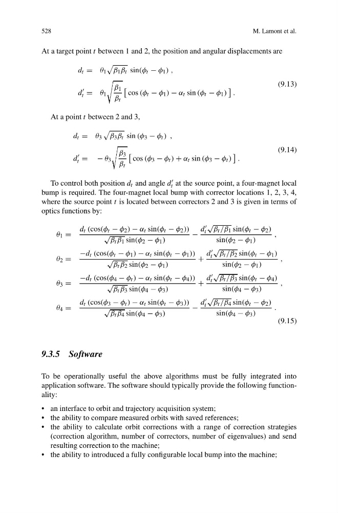
At a target point t between 1 and 2, the position and angular displacements are
d t = θ 1
β 1 β t sin(φ t − φ 1 ) ,
d
t = θ 1
β 1
β t
cos (φ t − φ 1 ) − α t sin (φ t − φ 1 )
.
(9.13)
At a point t between 2 and 3,
d t = θ 3
β 3 β t sin (φ 3 − φ t ) ,
d
t = −θ 3
β 3
β t
cos (φ 3 − φ t ) + α t sin (φ 3 − φ t )
.
(9.14)
To control both position d t and angle d
t at the source point, a four-magnet local
bump is required. The four-magnet local bump with corrector locations 1, 2, 3, 4,
where the source point t is located between correctors 2 and 3 is given in terms of
optics functions by:
θ 1 =
d t (cos(φ t − φ 2 ) − α t sin(φ t − φ 2 ))
√
β t β 1 sin(φ 2 − φ 1 )
−
d
t
√
β t /β 1 sin(φ t − φ 2 )
sin(φ 2 − φ 1 )
,
θ 2 =
−d t (cos(φ t − φ 1 ) − α t sin(φ t − φ 1 ))
√
β t β 2 sin(φ 2 − φ 1 )
+
d
t
√
β t /β 2 sin(φ t − φ 1 )
sin(φ 2 − φ 1 )
,
θ 3 =
−d t (cos(φ 4 − φ t ) − α t sin(φ t − φ 4 ))
√
β t β 3 sin(φ 4 − φ 3 )
+
d
t
√
β t /β 3 sin(φ t − φ 4 )
sin(φ 4 − φ 3 )
,
θ 4 =
d t (cos(φ 3 − φ t ) − α t sin(φ t − φ 3 ))
√
β t β 4 sin(φ 4 − φ 3 )
−
d
t
√
β t /β 4 sin(φ t − φ 2 )
sin(φ 4 − φ 3 )
.
(9.15)
9.3.5 Software
To be operationally useful the above algorithms must be fully integrated into
application software. The software should typically provide the following functionality:
• an interface to orbit and trajectory acquisition system;
• the ability to compare measured orbits with saved references;
• the ability to calculate orbit corrections with a range of correction strategies
(correction algorithm, number of correctors, number of eigenvalues) and send
resulting correction to the machine;
• the ability to introduced a fully configurable local bump into the machine;
M. Lamont et al.
At a target point t between 1 and 2, the position and angular displacements are
d t = θ 1
β 1 β t sin(φ t − φ 1 ) ,
d
t = θ 1
β 1
β t
cos (φ t − φ 1 ) − α t sin (φ t − φ 1 )
.
(9.13)
At a point t between 2 and 3,
d t = θ 3
β 3 β t sin (φ 3 − φ t ) ,
d
t = −θ 3
β 3
β t
cos (φ 3 − φ t ) + α t sin (φ 3 − φ t )
.
(9.14)
To control both position d t and angle d
t at the source point, a four-magnet local
bump is required. The four-magnet local bump with corrector locations 1, 2, 3, 4,
where the source point t is located between correctors 2 and 3 is given in terms of
optics functions by:
θ 1 =
d t (cos(φ t − φ 2 ) − α t sin(φ t − φ 2 ))
√
β t β 1 sin(φ 2 − φ 1 )
−
d
t
√
β t /β 1 sin(φ t − φ 2 )
sin(φ 2 − φ 1 )
,
θ 2 =
−d t (cos(φ t − φ 1 ) − α t sin(φ t − φ 1 ))
√
β t β 2 sin(φ 2 − φ 1 )
+
d
t
√
β t /β 2 sin(φ t − φ 1 )
sin(φ 2 − φ 1 )
,
θ 3 =
−d t (cos(φ 4 − φ t ) − α t sin(φ t − φ 4 ))
√
β t β 3 sin(φ 4 − φ 3 )
+
d
t
√
β t /β 3 sin(φ t − φ 4 )
sin(φ 4 − φ 3 )
,
θ 4 =
d t (cos(φ 3 − φ t ) − α t sin(φ t − φ 3 ))
√
β t β 4 sin(φ 4 − φ 3 )
−
d
t
√
β t /β 4 sin(φ t − φ 2 )
sin(φ 4 − φ 3 )
.
(9.15)
9.3.5 Software
To be operationally useful the above algorithms must be fully integrated into
application software. The software should typically provide the following functionality:
• an interface to orbit and trajectory acquisition system;
• the ability to compare measured orbits with saved references;
• the ability to calculate orbit corrections with a range of correction strategies
(correction algorithm, number of correctors, number of eigenvalues) and send
resulting correction to the machine;
• the ability to introduced a fully configurable local bump into the machine;