

8 Accelerator Engineering and Technology: Accelerator Technology
467
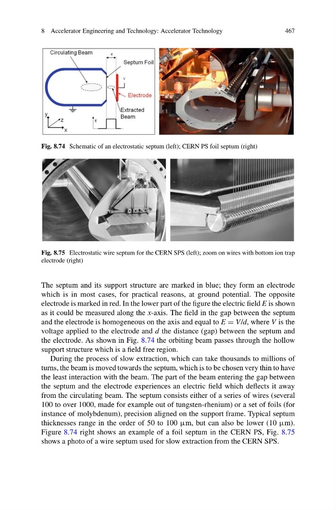
Fig. 8.74 Schematic of an electrostatic septum (left); CERN PS foil septum (right)
Fig. 8.75 Electrostatic wire septum for the CERN SPS (left); zoom on wires with bottom ion trap
electrode (right)
The septum and its support structure are marked in blue; they form an electrode
which is in most cases, for practical reasons, at ground potential. The opposite
electrode is marked in red. In the lower part of the figure the electric field E is shown
as it could be measured along the x-axis. The field in the gap between the septum
and the electrode is homogeneous on the axis and equal to E = V/d, where V is the
voltage applied to the electrode and d the distance (gap) between the septum and
the electrode. As shown in Fig. 8.74 the orbiting beam passes through the hollow
support structure which is a field free region.
During the process of slow extraction, which can take thousands to millions of
turns, the beam is moved towards the septum, which is to be chosen very thin to have
the least interaction with the beam. The part of the beam entering the gap between
the septum and the electrode experiences an electric field which deflects it away
from the circulating beam. The septum consists either of a series of wires (several
100 to over 1000, made for example out of tungsten-rhenium) or a set of foils (for
instance of molybdenum), precision aligned on the support frame. Typical septum
thicknesses range in the order of 50 to 100 μm, but can also be lower (10 μm).
Figure 8.74 right shows an example of a foil septum in the CERN PS, Fig. 8.75
shows a photo of a wire septum used for slow extraction from the CERN SPS.
467
Fig. 8.74 Schematic of an electrostatic septum (left); CERN PS foil septum (right)
Fig. 8.75 Electrostatic wire septum for the CERN SPS (left); zoom on wires with bottom ion trap
electrode (right)
The septum and its support structure are marked in blue; they form an electrode
which is in most cases, for practical reasons, at ground potential. The opposite
electrode is marked in red. In the lower part of the figure the electric field E is shown
as it could be measured along the x-axis. The field in the gap between the septum
and the electrode is homogeneous on the axis and equal to E = V/d, where V is the
voltage applied to the electrode and d the distance (gap) between the septum and
the electrode. As shown in Fig. 8.74 the orbiting beam passes through the hollow
support structure which is a field free region.
During the process of slow extraction, which can take thousands to millions of
turns, the beam is moved towards the septum, which is to be chosen very thin to have
the least interaction with the beam. The part of the beam entering the gap between
the septum and the electrode experiences an electric field which deflects it away
from the circulating beam. The septum consists either of a series of wires (several
100 to over 1000, made for example out of tungsten-rhenium) or a set of foils (for
instance of molybdenum), precision aligned on the support frame. Typical septum
thicknesses range in the order of 50 to 100 μm, but can also be lower (10 μm).
Figure 8.74 right shows an example of a foil septum in the CERN PS, Fig. 8.75
shows a photo of a wire septum used for slow extraction from the CERN SPS.