

462
F. Bordry et al.
8.7.1.3 Pulse Generation and Forming
The simplest pulse forming circuit consists of a coaxial cable (a pulse forming
line, PFL) charged to twice the required pulse voltage. A PFL provides fast and
low-ripple pulses but requires low dispersion and attenuation, especially for longer
pulses, to keep droop and “cable tail” within specification. Since semiconductor
materials in the cable (used to improve the breakdown voltage) increase the attenuation and dispersion, SF6 pressurized polyethylene (PE) cables have historically
been used for PFL voltages above 50 kV. The required length and cost of PFL cable,
as well as the attenuation and dispersion, limits the practical application to pulse
durations of less than approximately 3 μs.
Where long pulses with low droop are required, a PFN is used which acts as
artificial coaxial cable. The PFN consists of a series of “cells” forming a delay
line. There are many configurations for PFNs [177] but a commonly used design
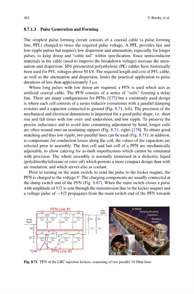
is where each cell consists of a series inductor (sometimes with a parallel damping
resistor) and a capacitor connected to ground (Fig. 8.71, left). The precision of the
mechanical and electrical dimensions is important for a good pulse shape, i.e. short
rise and fall times with low over- and undershoot, and low ripple. To preserve the
precise inductance and to avoid time consuming adjustment by hand, longer coils
are often wound onto an insulating support (Fig. 8.71, right) [178]. To obtain good
matching and thus low ripple, two parallel lines can be used (Fig. 8.71): in addition,
to compensate for conduction losses along the coil, the values of the capacitors are
selected prior to assembly. The first cell and last cell of a PFN are mechanically
adjustable, to allow catering for as-built imperfections which cannot be simulated
with precision. The whole assembly is normally immersed in a dielectric liquid
(polydimethylsiloxane or ester oil) which permits a more compact design than with
air insulation, and which serves also as coolant.
Prior to turning on the main switch, to send the pulse to the kicker magnet, the
PFN is charged to the voltage V. The charging components are usually connected at
the dump switch end of the PFN (Fig. 8.67). When the main switch closes a pulse
with amplitude of V/2 is sent through the transmission line to the kicker magnet and
a voltage pulse of −V/2 propagates from the main switch end of the PFN towards
PFN Line #1
PFN Line #2
L3
Rp3
Rp2
Rp2
Rp1
Rp3
Rp2
Rp2
Rp1
L2
C2
L1
C1
L2
C2
L3
L2
C2
L1
C1
L2
C2
Dump
Switch
CB
RB
C3
R3
Main
Switch
C4
R4
“Cell”
Fig. 8.71 PFN of the LHC injection kickers, consisting of two parallel 10 Ohm lines
F. Bordry et al.
8.7.1.3 Pulse Generation and Forming
The simplest pulse forming circuit consists of a coaxial cable (a pulse forming
line, PFL) charged to twice the required pulse voltage. A PFL provides fast and
low-ripple pulses but requires low dispersion and attenuation, especially for longer
pulses, to keep droop and “cable tail” within specification. Since semiconductor
materials in the cable (used to improve the breakdown voltage) increase the attenuation and dispersion, SF6 pressurized polyethylene (PE) cables have historically
been used for PFL voltages above 50 kV. The required length and cost of PFL cable,
as well as the attenuation and dispersion, limits the practical application to pulse
durations of less than approximately 3 μs.
Where long pulses with low droop are required, a PFN is used which acts as
artificial coaxial cable. The PFN consists of a series of “cells” forming a delay
line. There are many configurations for PFNs [177] but a commonly used design
is where each cell consists of a series inductor (sometimes with a parallel damping
resistor) and a capacitor connected to ground (Fig. 8.71, left). The precision of the
mechanical and electrical dimensions is important for a good pulse shape, i.e. short
rise and fall times with low over- and undershoot, and low ripple. To preserve the
precise inductance and to avoid time consuming adjustment by hand, longer coils
are often wound onto an insulating support (Fig. 8.71, right) [178]. To obtain good
matching and thus low ripple, two parallel lines can be used (Fig. 8.71): in addition,
to compensate for conduction losses along the coil, the values of the capacitors are
selected prior to assembly. The first cell and last cell of a PFN are mechanically
adjustable, to allow catering for as-built imperfections which cannot be simulated
with precision. The whole assembly is normally immersed in a dielectric liquid
(polydimethylsiloxane or ester oil) which permits a more compact design than with
air insulation, and which serves also as coolant.
Prior to turning on the main switch, to send the pulse to the kicker magnet, the
PFN is charged to the voltage V. The charging components are usually connected at
the dump switch end of the PFN (Fig. 8.67). When the main switch closes a pulse
with amplitude of V/2 is sent through the transmission line to the kicker magnet and
a voltage pulse of −V/2 propagates from the main switch end of the PFN towards
PFN Line #1
PFN Line #2
L3
Rp3
Rp2
Rp2
Rp1
Rp3
Rp2
Rp2
Rp1
L2
C2
L1
C1
L2
C2
L3
L2
C2
L1
C1
L2
C2
Dump
Switch
CB
RB
C3
R3
Main
Switch
C4
R4
“Cell”
Fig. 8.71 PFN of the LHC injection kickers, consisting of two parallel 10 Ohm lines