

8 Accelerator Engineering and Technology: Accelerator Technology
403
Table 8.16 Maximum
values of Joule-Thomson
inversion temperature
Cryogen
Maximum inversion temperature [K]
Helium
43
Hydrogen 202
Neon
260
Air
603
Nitrogen
623
Oxygen
761
'liquefactor load'
(back to compressor at ambient temperature)
compressor
power input
aftercooler
(heat output)
turbines
in parallel
TU1
TU2
'refrigerator
load'
(isothermal)
HX1
HX2
HX3
HX4
HX5
S
log T
compressor
HX1
HX2
HX3
HX4
HX5
TU1
TU2
aftercooler
JT
JT
HP
LP
LP
HP
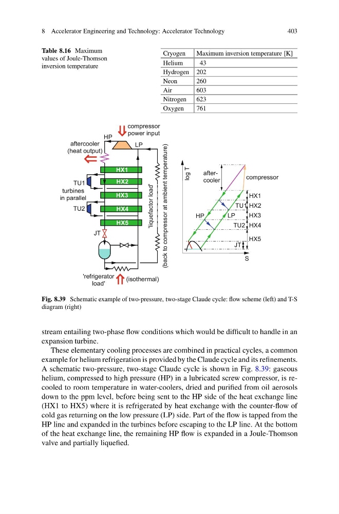
Fig. 8.39 Schematic example of two-pressure, two-stage Claude cycle: flow scheme (left) and T-S
diagram (right)
stream entailing two-phase flow conditions which would be difficult to handle in an
expansion turbine.
These elementary cooling processes are combined in practical cycles, a common
example for helium refrigeration is provided by the Claude cycle and its refinements.
A schematic two-pressure, two-stage Claude cycle is shown in Fig. 8.39: gaseous
helium, compressed to high pressure (HP) in a lubricated screw compressor, is recooled to room temperature in water-coolers, dried and purified from oil aerosols
down to the ppm level, before being sent to the HP side of the heat exchange line
(HX1 to HX5) where it is refrigerated by heat exchange with the counter-flow of
cold gas returning on the low pressure (LP) side. Part of the flow is tapped from the
HP line and expanded in the turbines before escaping to the LP line. At the bottom
of the heat exchange line, the remaining HP flow is expanded in a Joule-Thomson
valve and partially liquefied.
403
Table 8.16 Maximum
values of Joule-Thomson
inversion temperature
Cryogen
Maximum inversion temperature [K]
Helium
43
Hydrogen 202
Neon
260
Air
603
Nitrogen
623
Oxygen
761
'liquefactor load'
(back to compressor at ambient temperature)
compressor
power input
aftercooler
(heat output)
turbines
in parallel
TU1
TU2
'refrigerator
load'
(isothermal)
HX1
HX2
HX3
HX4
HX5
S
log T
compressor
HX1
HX2
HX3
HX4
HX5
TU1
TU2
aftercooler
JT
JT
HP
LP
LP
HP
Fig. 8.39 Schematic example of two-pressure, two-stage Claude cycle: flow scheme (left) and T-S
diagram (right)
stream entailing two-phase flow conditions which would be difficult to handle in an
expansion turbine.
These elementary cooling processes are combined in practical cycles, a common
example for helium refrigeration is provided by the Claude cycle and its refinements.
A schematic two-pressure, two-stage Claude cycle is shown in Fig. 8.39: gaseous
helium, compressed to high pressure (HP) in a lubricated screw compressor, is recooled to room temperature in water-coolers, dried and purified from oil aerosols
down to the ppm level, before being sent to the HP side of the heat exchange line
(HX1 to HX5) where it is refrigerated by heat exchange with the counter-flow of
cold gas returning on the low pressure (LP) side. Part of the flow is tapped from the
HP line and expanded in the turbines before escaping to the LP line. At the bottom
of the heat exchange line, the remaining HP flow is expanded in a Joule-Thomson
valve and partially liquefied.