

384
F. Bordry et al.
For the construction of crab cavities for the LHC, RF engineers were confronted
with an additional difficulty resulting from the proximity of the two beam pipes,
which in most of the machine are spaced by only 194 mm. Conventional, elliptically
shaped RF cavities have a radius of roughly half a wavelength, which in the case of
LHC is not consistent at a frequency of 400 MHz. A special straight section near
point 4 is provided for the 400 MHz accelerating cavities described in Sect. 8.2.7
above, but it is desirable that the crab cavities are located upstream and downstream
of the high luminosity collision points.
In a rigorous R&D program over recent years, a collaboration between CERN,
FNAL, JLAB, BNL, LBNL and ODU in the US, the STFC in the UK, KEK in
Japan and industry has successfully designed, prototyped, fabricated and tested crab
cavities compact enough to meet the demanding LHC constraints and specifications.
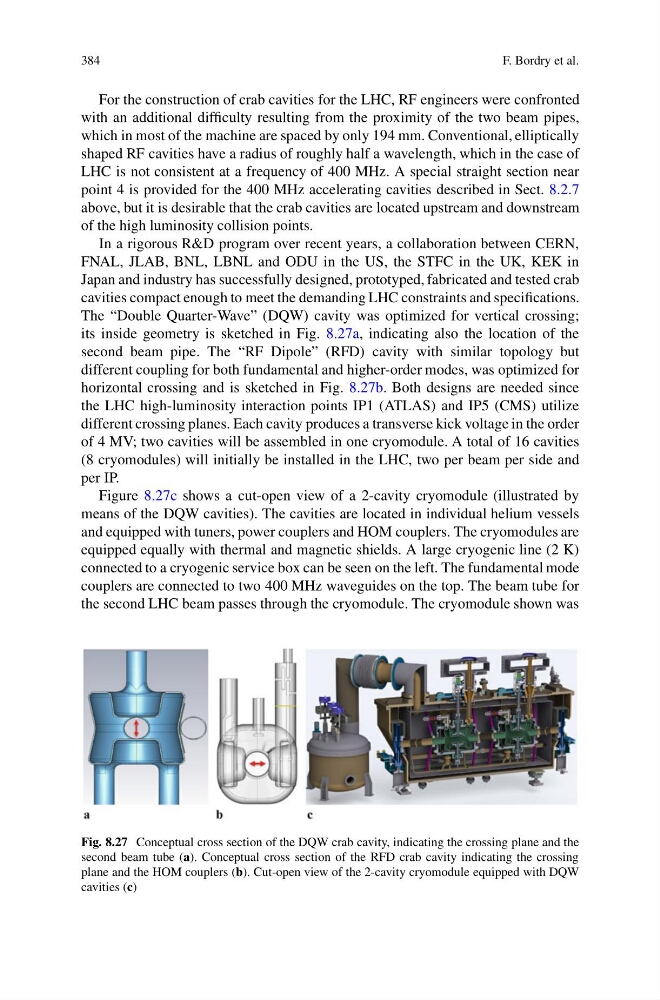
The “Double Quarter-Wave” (DQW) cavity was optimized for vertical crossing;
its inside geometry is sketched in Fig. 8.27a, indicating also the location of the
second beam pipe. The “RF Dipole” (RFD) cavity with similar topology but
different coupling for both fundamental and higher-order modes, was optimized for
horizontal crossing and is sketched in Fig. 8.27b. Both designs are needed since
the LHC high-luminosity interaction points IP1 (ATLAS) and IP5 (CMS) utilize
different crossing planes. Each cavity produces a transverse kick voltage in the order
of 4 MV; two cavities will be assembled in one cryomodule. A total of 16 cavities
(8 cryomodules) will initially be installed in the LHC, two per beam per side and
per IP.
Figure 8.27c shows a cut-open view of a 2-cavity cryomodule (illustrated by
means of the DQW cavities). The cavities are located in individual helium vessels
and equipped with tuners, power couplers and HOM couplers. The cryomodules are
equipped equally with thermal and magnetic shields. A large cryogenic line (2 K)
connected to a cryogenic service box can be seen on the left. The fundamental mode
couplers are connected to two 400 MHz waveguides on the top. The beam tube for
the second LHC beam passes through the cryomodule. The cryomodule shown was
Fig. 8.27 Conceptual cross section of the DQW crab cavity, indicating the crossing plane and the
second beam tube (a). Conceptual cross section of the RFD crab cavity indicating the crossing
plane and the HOM couplers (b). Cut-open view of the 2-cavity cryomodule equipped with DQW
cavities (c)
F. Bordry et al.
For the construction of crab cavities for the LHC, RF engineers were confronted
with an additional difficulty resulting from the proximity of the two beam pipes,
which in most of the machine are spaced by only 194 mm. Conventional, elliptically
shaped RF cavities have a radius of roughly half a wavelength, which in the case of
LHC is not consistent at a frequency of 400 MHz. A special straight section near
point 4 is provided for the 400 MHz accelerating cavities described in Sect. 8.2.7
above, but it is desirable that the crab cavities are located upstream and downstream
of the high luminosity collision points.
In a rigorous R&D program over recent years, a collaboration between CERN,
FNAL, JLAB, BNL, LBNL and ODU in the US, the STFC in the UK, KEK in
Japan and industry has successfully designed, prototyped, fabricated and tested crab
cavities compact enough to meet the demanding LHC constraints and specifications.
The “Double Quarter-Wave” (DQW) cavity was optimized for vertical crossing;
its inside geometry is sketched in Fig. 8.27a, indicating also the location of the
second beam pipe. The “RF Dipole” (RFD) cavity with similar topology but
different coupling for both fundamental and higher-order modes, was optimized for
horizontal crossing and is sketched in Fig. 8.27b. Both designs are needed since
the LHC high-luminosity interaction points IP1 (ATLAS) and IP5 (CMS) utilize
different crossing planes. Each cavity produces a transverse kick voltage in the order
of 4 MV; two cavities will be assembled in one cryomodule. A total of 16 cavities
(8 cryomodules) will initially be installed in the LHC, two per beam per side and
per IP.
Figure 8.27c shows a cut-open view of a 2-cavity cryomodule (illustrated by
means of the DQW cavities). The cavities are located in individual helium vessels
and equipped with tuners, power couplers and HOM couplers. The cryomodules are
equipped equally with thermal and magnetic shields. A large cryogenic line (2 K)
connected to a cryogenic service box can be seen on the left. The fundamental mode
couplers are connected to two 400 MHz waveguides on the top. The beam tube for
the second LHC beam passes through the cryomodule. The cryomodule shown was
Fig. 8.27 Conceptual cross section of the DQW crab cavity, indicating the crossing plane and the
second beam tube (a). Conceptual cross section of the RFD crab cavity indicating the crossing
plane and the HOM couplers (b). Cut-open view of the 2-cavity cryomodule equipped with DQW
cavities (c)