

8 Accelerator Engineering and Technology: Accelerator Technology
375
Fig. 8.17 Schematic of a
ferrite cavity. The bias current
allows magnetization of the
ferrite rings which influences
the resonant frequency
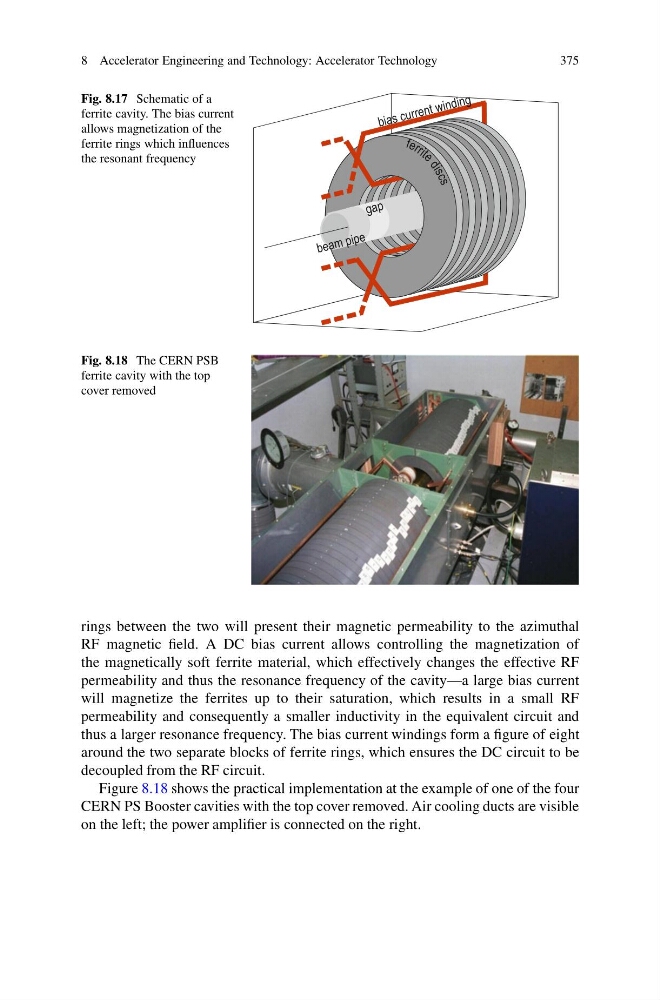
Fig. 8.18 The CERN PSB
ferrite cavity with the top
cover removed
rings between the two will present their magnetic permeability to the azimuthal
RF magnetic field. A DC bias current allows controlling the magnetization of
the magnetically soft ferrite material, which effectively changes the effective RF
permeability and thus the resonance frequency of the cavity—a large bias current
will magnetize the ferrites up to their saturation, which results in a small RF
permeability and consequently a smaller inductivity in the equivalent circuit and
thus a larger resonance frequency. The bias current windings form a figure of eight
around the two separate blocks of ferrite rings, which ensures the DC circuit to be
decoupled from the RF circuit.
Figure 8.18 shows the practical implementation at the example of one of the four
CERN PS Booster cavities with the top cover removed. Air cooling ducts are visible
on the left; the power amplifier is connected on the right.
375
Fig. 8.17 Schematic of a
ferrite cavity. The bias current
allows magnetization of the
ferrite rings which influences
the resonant frequency
Fig. 8.18 The CERN PSB
ferrite cavity with the top
cover removed
rings between the two will present their magnetic permeability to the azimuthal
RF magnetic field. A DC bias current allows controlling the magnetization of
the magnetically soft ferrite material, which effectively changes the effective RF
permeability and thus the resonance frequency of the cavity—a large bias current
will magnetize the ferrites up to their saturation, which results in a small RF
permeability and consequently a smaller inductivity in the equivalent circuit and
thus a larger resonance frequency. The bias current windings form a figure of eight
around the two separate blocks of ferrite rings, which ensures the DC circuit to be
decoupled from the RF circuit.
Figure 8.18 shows the practical implementation at the example of one of the four
CERN PS Booster cavities with the top cover removed. Air cooling ducts are visible
on the left; the power amplifier is connected on the right.