

346
F. Bordry et al.
Introducing l av as the average coil turn length, it is easy to show that the power
dissipated in a magnet is:
P dipole = ρ
B rms g
ημ 0
J rms l av ; P quadrupole = 2ρ
G rms R 2
ημ 0
J rms l av ; P sextupole = ρ
B" rms R 3
ημ 0
J rms l av .
(8.11)
In case of water-cooled magnets, heat is removed by water circulating in the coil
(hollow) conductors.
The choice of cooling parameters and number of circuits is based on a few main
principles: set the water flow corresponding to the allowed temperature drop for a
given power to be removed, having a moderate turbulent flow to provide an efficient
cooling, keeping the water velocity within reasonable limits to avoid erosioncorrosion and impingement of the cooling pipes and of the junctions, keeping the
pressure drop across the circuit within reasonable limits (typically within 10–15
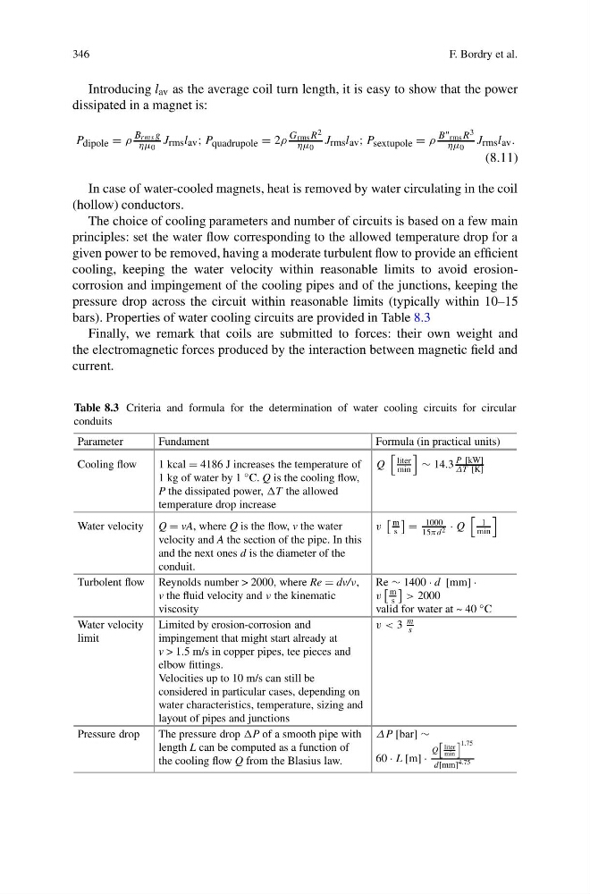
bars). Properties of water cooling circuits are provided in Table 8.3
Finally, we remark that coils are submitted to forces: their own weight and
the electromagnetic forces produced by the interaction between magnetic field and
current.
Table 8.3 Criteria and formula for the determination of water cooling circuits for circular
conduits
Parameter
Fundament
Formula (in practical units)
Cooling flow
1 kcal = 4186 J increases the temperature of
1 kg of water by 1 ◦ C. Q is the cooling flow,
P the dissipated power, the allowed
temperature drop increase
Q
liter
min
∼ 14.3
P [kW]
ΔT [K]
Water velocity Q = vA, where Q is the flow, v the water
velocity and A the section of the pipe. In this
and the next ones d is the diameter of the
conduit.
v
m
s
=
1000
15πd 2 · Q
l
min
Turbolent flow Reynolds number > 2000, where Re = dv/ν,
v the fluid velocity and ν the kinematic
viscosity
Re ∼ 1400 · d [mm] ·
v
m
s
> 2000
valid for water at ~ 40 ◦ C
Water velocity
limit
Limited by erosion-corrosion and
impingement that might start already at
v > 1.5 m/s in copper pipes, tee pieces and
elbow fittings.
Velocities up to 10 m/s can still be
considered in particular cases, depending on
water characteristics, temperature, sizing and
layout of pipes and junctions
v < 3
m
s
Pressure drop
The pressure drop of a smooth pipe with
length L can be computed as a function of
the cooling flow Q from the Blasius law.
ΔP [bar] ∼
60 · L [m] ·
Q
liter
min
1.75
d[mm] 4.75
F. Bordry et al.
Introducing l av as the average coil turn length, it is easy to show that the power
dissipated in a magnet is:
P dipole = ρ
B rms g
ημ 0
J rms l av ; P quadrupole = 2ρ
G rms R 2
ημ 0
J rms l av ; P sextupole = ρ
B" rms R 3
ημ 0
J rms l av .
(8.11)
In case of water-cooled magnets, heat is removed by water circulating in the coil
(hollow) conductors.
The choice of cooling parameters and number of circuits is based on a few main
principles: set the water flow corresponding to the allowed temperature drop for a
given power to be removed, having a moderate turbulent flow to provide an efficient
cooling, keeping the water velocity within reasonable limits to avoid erosioncorrosion and impingement of the cooling pipes and of the junctions, keeping the
pressure drop across the circuit within reasonable limits (typically within 10–15
bars). Properties of water cooling circuits are provided in Table 8.3
Finally, we remark that coils are submitted to forces: their own weight and
the electromagnetic forces produced by the interaction between magnetic field and
current.
Table 8.3 Criteria and formula for the determination of water cooling circuits for circular
conduits
Parameter
Fundament
Formula (in practical units)
Cooling flow
1 kcal = 4186 J increases the temperature of
1 kg of water by 1 ◦ C. Q is the cooling flow,
P the dissipated power, the allowed
temperature drop increase
Q
liter
min
∼ 14.3
P [kW]
ΔT [K]
Water velocity Q = vA, where Q is the flow, v the water
velocity and A the section of the pipe. In this
and the next ones d is the diameter of the
conduit.
v
m
s
=
1000
15πd 2 · Q
l
min
Turbolent flow Reynolds number > 2000, where Re = dv/ν,
v the fluid velocity and ν the kinematic
viscosity
Re ∼ 1400 · d [mm] ·
v
m
s
> 2000
valid for water at ~ 40 ◦ C
Water velocity
limit
Limited by erosion-corrosion and
impingement that might start already at
v > 1.5 m/s in copper pipes, tee pieces and
elbow fittings.
Velocities up to 10 m/s can still be
considered in particular cases, depending on
water characteristics, temperature, sizing and
layout of pipes and junctions
v < 3
m
s
Pressure drop
The pressure drop of a smooth pipe with
length L can be computed as a function of
the cooling flow Q from the Blasius law.
ΔP [bar] ∼
60 · L [m] ·
Q
liter
min
1.75
d[mm] 4.75