

7 Design and Principles of Linear Accelerators and Colliders
323
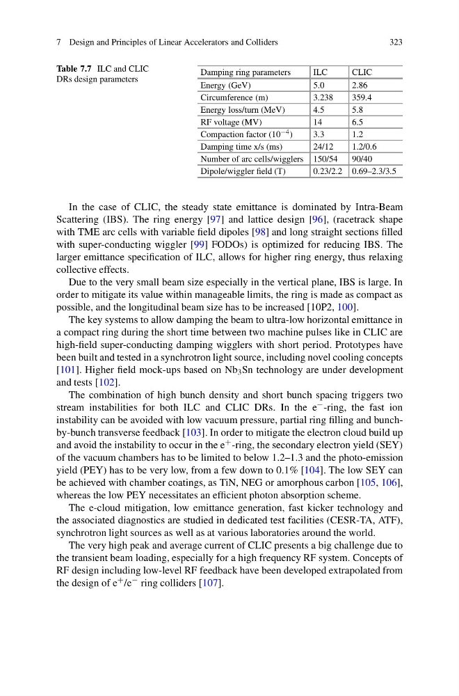
Table 7.7 ILC and CLIC
DRs design parameters
Damping ring parameters
ILC
CLIC
Energy (GeV)
5.0
2.86
Circumference (m)
3.238
359.4
Energy loss/turn (MeV)
4.5
5.8
RF voltage (MV)
14
6.5
Compaction factor (10 −4 )
3.3
1.2
Damping time x/s (ms)
24/12
1.2/0.6
Number of arc cells/wigglers 150/54
90/40
Dipole/wiggler field (T)
0.23/2.2 0.69–2.3/3.5
In the case of CLIC, the steady state emittance is dominated by Intra-Beam
Scattering (IBS). The ring energy [97] and lattice design [96], (racetrack shape
with TME arc cells with variable field dipoles [98] and long straight sections filled
with super-conducting wiggler [99] FODOs) is optimized for reducing IBS. The
larger emittance specification of ILC, allows for higher ring energy, thus relaxing
collective effects.
Due to the very small beam size especially in the vertical plane, IBS is large. In
order to mitigate its value within manageable limits, the ring is made as compact as
possible, and the longitudinal beam size has to be increased [10P2, 100].
The key systems to allow damping the beam to ultra-low horizontal emittance in
a compact ring during the short time between two machine pulses like in CLIC are
high-field super-conducting damping wigglers with short period. Prototypes have
been built and tested in a synchrotron light source, including novel cooling concepts
[101]. Higher field mock-ups based on Nb 3 Sn technology are under development
and tests [102].
The combination of high bunch density and short bunch spacing triggers two
stream instabilities for both ILC and CLIC DRs. In the e − -ring, the fast ion
instability can be avoided with low vacuum pressure, partial ring filling and bunchby-bunch transverse feedback [103]. In order to mitigate the electron cloud build up
and avoid the instability to occur in the e + -ring, the secondary electron yield (SEY)
of the vacuum chambers has to be limited to below 1.2–1.3 and the photo-emission
yield (PEY) has to be very low, from a few down to 0.1% [104]. The low SEY can
be achieved with chamber coatings, as TiN, NEG or amorphous carbon [105, 106],
whereas the low PEY necessitates an efficient photon absorption scheme.
The e-cloud mitigation, low emittance generation, fast kicker technology and
the associated diagnostics are studied in dedicated test facilities (CESR-TA, ATF),
synchrotron light sources as well as at various laboratories around the world.
The very high peak and average current of CLIC presents a big challenge due to
the transient beam loading, especially for a high frequency RF system. Concepts of
RF design including low-level RF feedback have been developed extrapolated from
the design of e + /e − ring colliders [107].
323
Table 7.7 ILC and CLIC
DRs design parameters
Damping ring parameters
ILC
CLIC
Energy (GeV)
5.0
2.86
Circumference (m)
3.238
359.4
Energy loss/turn (MeV)
4.5
5.8
RF voltage (MV)
14
6.5
Compaction factor (10 −4 )
3.3
1.2
Damping time x/s (ms)
24/12
1.2/0.6
Number of arc cells/wigglers 150/54
90/40
Dipole/wiggler field (T)
0.23/2.2 0.69–2.3/3.5
In the case of CLIC, the steady state emittance is dominated by Intra-Beam
Scattering (IBS). The ring energy [97] and lattice design [96], (racetrack shape
with TME arc cells with variable field dipoles [98] and long straight sections filled
with super-conducting wiggler [99] FODOs) is optimized for reducing IBS. The
larger emittance specification of ILC, allows for higher ring energy, thus relaxing
collective effects.
Due to the very small beam size especially in the vertical plane, IBS is large. In
order to mitigate its value within manageable limits, the ring is made as compact as
possible, and the longitudinal beam size has to be increased [10P2, 100].
The key systems to allow damping the beam to ultra-low horizontal emittance in
a compact ring during the short time between two machine pulses like in CLIC are
high-field super-conducting damping wigglers with short period. Prototypes have
been built and tested in a synchrotron light source, including novel cooling concepts
[101]. Higher field mock-ups based on Nb 3 Sn technology are under development
and tests [102].
The combination of high bunch density and short bunch spacing triggers two
stream instabilities for both ILC and CLIC DRs. In the e − -ring, the fast ion
instability can be avoided with low vacuum pressure, partial ring filling and bunchby-bunch transverse feedback [103]. In order to mitigate the electron cloud build up
and avoid the instability to occur in the e + -ring, the secondary electron yield (SEY)
of the vacuum chambers has to be limited to below 1.2–1.3 and the photo-emission
yield (PEY) has to be very low, from a few down to 0.1% [104]. The low SEY can
be achieved with chamber coatings, as TiN, NEG or amorphous carbon [105, 106],
whereas the low PEY necessitates an efficient photon absorption scheme.
The e-cloud mitigation, low emittance generation, fast kicker technology and
the associated diagnostics are studied in dedicated test facilities (CESR-TA, ATF),
synchrotron light sources as well as at various laboratories around the world.
The very high peak and average current of CLIC presents a big challenge due to
the transient beam loading, especially for a high frequency RF system. Concepts of
RF design including low-level RF feedback have been developed extrapolated from
the design of e + /e − ring colliders [107].