

312
J. Seeman et al.
7.4.2 Superconducting Accelerating Structures
Linear accelerators have benefitted greatly through the use of superconducting
radio-frequency (SCRF) cavity technology [1, 57]. This technology, when applied
in standing-wave RF operation, provides the following important advantages:
• Small RF surface resistance and large quality factor, Q, resulting long pulse operation, with a range of 1 ms, and much higher duty factor in beam acceleration.
• Lower operational frequency with enlarged beam-apertures in the range of
~70 mm diameter, (1.3 GHz), resulting in large acceptance and providing
practical solutions for very intense beams.
Two salient characteristics of superconducting cavities are (1) the average
accelerating field gradient E acc and (2) the intrinsic quality factor Q. Quality factor
Q is a universal figure of merit for resonators and is defined in the usual manner as
the ratio of the energy, U, stored in the cavity to the power, P c , lost in one RF period.
Q depends on the microwave surface resistance of the metal. In general, one would
like to have as high accelerating field and as high Q as possible.
The strongest incentive to use superconducting cavities in an accelerator is that
continuous wave (CW) mode or high duty factor (>1%) operation is practical. For
CW operation power dissipation in the walls of a copper structure is substantial
and often not possible. Here superconductivity comes to the rescue. The microwave
surface resistance of a superconductor is typically five orders of magnitude lower
than that of copper, and therefore the Q value is five orders of magnitude higher [58].
The above advantages may be of benefit even though superconducting technology
requires low temperature (1.8 K) cryogenic system operation, resulting additional
power consumption, discussed below.
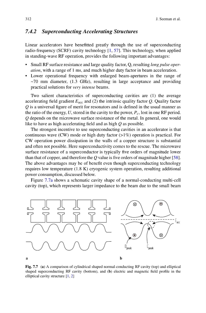
Figure 7.7a shows a schematic cavity shape of a normal-conducting multi-cell
cavity (top), which represents larger impedance to the beam due to the small beam
Fig. 7.7 (a) A comparison of cylindrical shaped normal-conducting RF cavity (top) and elliptical
shaped superconducting RF cavity (bottom), and (b) electric and magnetic field profile in the
elliptical cavity structure [1, 2]
J. Seeman et al.
7.4.2 Superconducting Accelerating Structures
Linear accelerators have benefitted greatly through the use of superconducting
radio-frequency (SCRF) cavity technology [1, 57]. This technology, when applied
in standing-wave RF operation, provides the following important advantages:
• Small RF surface resistance and large quality factor, Q, resulting long pulse operation, with a range of 1 ms, and much higher duty factor in beam acceleration.
• Lower operational frequency with enlarged beam-apertures in the range of
~70 mm diameter, (1.3 GHz), resulting in large acceptance and providing
practical solutions for very intense beams.
Two salient characteristics of superconducting cavities are (1) the average
accelerating field gradient E acc and (2) the intrinsic quality factor Q. Quality factor
Q is a universal figure of merit for resonators and is defined in the usual manner as
the ratio of the energy, U, stored in the cavity to the power, P c , lost in one RF period.
Q depends on the microwave surface resistance of the metal. In general, one would
like to have as high accelerating field and as high Q as possible.
The strongest incentive to use superconducting cavities in an accelerator is that
continuous wave (CW) mode or high duty factor (>1%) operation is practical. For
CW operation power dissipation in the walls of a copper structure is substantial
and often not possible. Here superconductivity comes to the rescue. The microwave
surface resistance of a superconductor is typically five orders of magnitude lower
than that of copper, and therefore the Q value is five orders of magnitude higher [58].
The above advantages may be of benefit even though superconducting technology
requires low temperature (1.8 K) cryogenic system operation, resulting additional
power consumption, discussed below.
Figure 7.7a shows a schematic cavity shape of a normal-conducting multi-cell
cavity (top), which represents larger impedance to the beam due to the small beam
Fig. 7.7 (a) A comparison of cylindrical shaped normal-conducting RF cavity (top) and elliptical
shaped superconducting RF cavity (bottom), and (b) electric and magnetic field profile in the
elliptical cavity structure [1, 2]