

7 Design and Principles of Linear Accelerators and Colliders
309
being developed for several decades, in the frequency range from few hundreds of
megahertz to a few gigahertz, with improving performances as described below in
Sect. 7.4.2.
7.4.1 Normal Conducting Accelerating Structures
In normal conducting (NC) linacs, acceleration of charged particles using RF power
is typically done in a chain of cavities (cells) which are strongly coupled and
where the electromagnetic wave propagates through the cells from the input to
the output of the structure. This allows a single RF source to feed many cells via
single input coupler thus minimizing the feeding waveguide network. The chain of
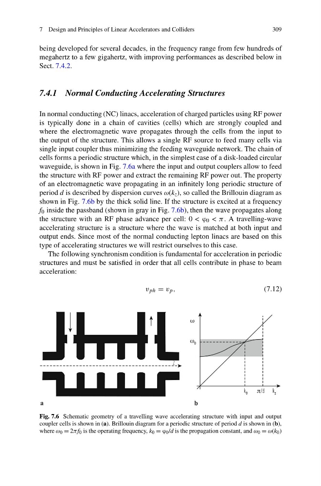
cells forms a periodic structure which, in the simplest case of a disk-loaded circular
waveguide, is shown in Fig. 7.6a where the input and output couplers allow to feed
the structure with RF power and extract the remaining RF power out. The property
of an electromagnetic wave propagating in an infinitely long periodic structure of
period d is described by dispersion curves ω(k z ), so called the Brillouin diagram as
shown in Fig. 7.6b by the thick solid line. If the structure is excited at a frequency
f 0 inside the passband (shown in gray in Fig. 7.6b), then the wave propagates along
the structure with an RF phase advance per cell: 0 < ϕ 0 < π. A travelling-wave
accelerating structure is a structure where the wave is matched at both input and
output ends. Since most of the normal conducting lepton linacs are based on this
type of accelerating structures we will restrict ourselves to this case.
The following synchronism condition is fundamental for acceleration in periodic
structures and must be satisfied in order that all cells contribute in phase to beam
acceleration:
v ph = v p ,
(7.12)
Fig. 7.6 Schematic geometry of a travelling wave accelerating structure with input and output
coupler cells is shown in (a). Brillouin diagram for a periodic structure of period d is shown in (b),
where ω 0 = 2πf 0 is the operating frequency, k 0 = ϕ 0 /d is the propagation constant, and ω 0 = ω(k 0 )
309
being developed for several decades, in the frequency range from few hundreds of
megahertz to a few gigahertz, with improving performances as described below in
Sect. 7.4.2.
7.4.1 Normal Conducting Accelerating Structures
In normal conducting (NC) linacs, acceleration of charged particles using RF power
is typically done in a chain of cavities (cells) which are strongly coupled and
where the electromagnetic wave propagates through the cells from the input to
the output of the structure. This allows a single RF source to feed many cells via
single input coupler thus minimizing the feeding waveguide network. The chain of
cells forms a periodic structure which, in the simplest case of a disk-loaded circular
waveguide, is shown in Fig. 7.6a where the input and output couplers allow to feed
the structure with RF power and extract the remaining RF power out. The property
of an electromagnetic wave propagating in an infinitely long periodic structure of
period d is described by dispersion curves ω(k z ), so called the Brillouin diagram as
shown in Fig. 7.6b by the thick solid line. If the structure is excited at a frequency
f 0 inside the passband (shown in gray in Fig. 7.6b), then the wave propagates along
the structure with an RF phase advance per cell: 0 < ϕ 0 < π. A travelling-wave
accelerating structure is a structure where the wave is matched at both input and
output ends. Since most of the normal conducting lepton linacs are based on this
type of accelerating structures we will restrict ourselves to this case.
The following synchronism condition is fundamental for acceleration in periodic
structures and must be satisfied in order that all cells contribute in phase to beam
acceleration:
v ph = v p ,
(7.12)
Fig. 7.6 Schematic geometry of a travelling wave accelerating structure with input and output
coupler cells is shown in (a). Brillouin diagram for a periodic structure of period d is shown in (b),
where ω 0 = 2πf 0 is the operating frequency, k 0 = ϕ 0 /d is the propagation constant, and ω 0 = ω(k 0 )