

224
B. J. Holzer et al.
6.3.2 Slip-Stacking Injection
In slip-stacking [15], two trains of bunches are merged to increase the bunch
intensity, using separate RF systems. A first train of bunches is injected on the closed
orbit and captured by the first RF system. This train of bunches is then decelerated,
and as a result circulates on a different orbit. A second batch is then injected on the
closed orbit and captured by the second RF system. The two trains of bunches have
slightly different energies and can be made to move relative to each other in phase.
When the phase difference reaches zero, both sets of bunches are captured together
and merged, by a rapid change of the RF frequency. The accelerator needs enough
momentum aperture to accept both beams, and sophisticated RF control to make
the manipulations. The final longitudinal emittance is the sum of the two individual
emittances multiplied by an unavoidable blowup factor, typically around 1.5.
6.3.3 H − Charge-Exchange Injection
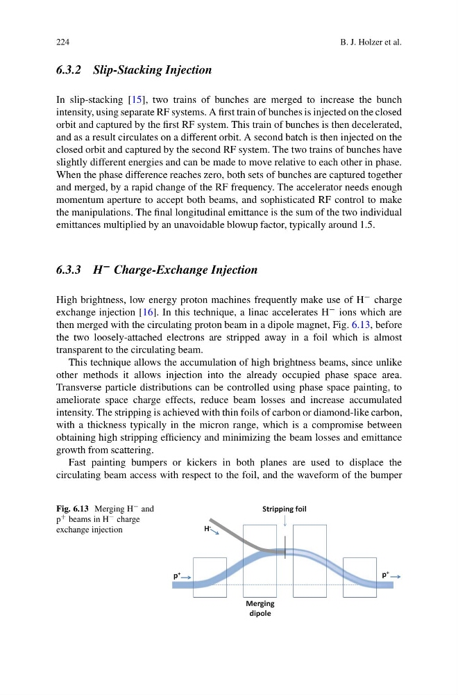
High brightness, low energy proton machines frequently make use of H − charge
exchange injection [16]. In this technique, a linac accelerates H − ions which are
then merged with the circulating proton beam in a dipole magnet, Fig. 6.13, before
the two loosely-attached electrons are stripped away in a foil which is almost
transparent to the circulating beam.
This technique allows the accumulation of high brightness beams, since unlike
other methods it allows injection into the already occupied phase space area.
Transverse particle distributions can be controlled using phase space painting, to
ameliorate space charge effects, reduce beam losses and increase accumulated
intensity. The stripping is achieved with thin foils of carbon or diamond-like carbon,
with a thickness typically in the micron range, which is a compromise between
obtaining high stripping efficiency and minimizing the beam losses and emittance
growth from scattering.
Fast painting bumpers or kickers in both planes are used to displace the
circulating beam access with respect to the foil, and the waveform of the bumper
Fig. 6.13 Merging H − and
p + beams in H − charge
exchange injection
H -
p +
p +
Stripping foil
Merging
dipole
B. J. Holzer et al.
6.3.2 Slip-Stacking Injection
In slip-stacking [15], two trains of bunches are merged to increase the bunch
intensity, using separate RF systems. A first train of bunches is injected on the closed
orbit and captured by the first RF system. This train of bunches is then decelerated,
and as a result circulates on a different orbit. A second batch is then injected on the
closed orbit and captured by the second RF system. The two trains of bunches have
slightly different energies and can be made to move relative to each other in phase.
When the phase difference reaches zero, both sets of bunches are captured together
and merged, by a rapid change of the RF frequency. The accelerator needs enough
momentum aperture to accept both beams, and sophisticated RF control to make
the manipulations. The final longitudinal emittance is the sum of the two individual
emittances multiplied by an unavoidable blowup factor, typically around 1.5.
6.3.3 H − Charge-Exchange Injection
High brightness, low energy proton machines frequently make use of H − charge
exchange injection [16]. In this technique, a linac accelerates H − ions which are
then merged with the circulating proton beam in a dipole magnet, Fig. 6.13, before
the two loosely-attached electrons are stripped away in a foil which is almost
transparent to the circulating beam.
This technique allows the accumulation of high brightness beams, since unlike
other methods it allows injection into the already occupied phase space area.
Transverse particle distributions can be controlled using phase space painting, to
ameliorate space charge effects, reduce beam losses and increase accumulated
intensity. The stripping is achieved with thin foils of carbon or diamond-like carbon,
with a thickness typically in the micron range, which is a compromise between
obtaining high stripping efficiency and minimizing the beam losses and emittance
growth from scattering.
Fast painting bumpers or kickers in both planes are used to displace the
circulating beam access with respect to the foil, and the waveform of the bumper
Fig. 6.13 Merging H − and
p + beams in H − charge
exchange injection
H -
p +
p +
Stripping foil
Merging
dipole