

7 Ionic Liquid–Liquid Chromatography: A Novel Separation Method
177
be used to calculate phase volumes in the coil. A dead volume of 4.0 cm
3 must be
taken into account, and the ratio of the phase volumes is accurate to ±0.5%.
In Fig. 7.7, it can be seen that there are considerable differences between the
behavior of the two phases in the four coils. The rate of loss of ionic liquid stationary
phase is dependent on both the coil diameter and length. For example, coils 1 and
3 have the same internal diameter but have completely different phase retention
curves (Fig. 7.7). This observation indicates that the stationary phase is not evenly
distributed in the coil during operation, and is concentrated at the head of the coil.
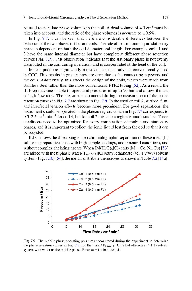
Ionic liquids are significantly more viscous than solvents conventionally used
in CCC. This results in greater pressure drop due to the connecting pipework and
the coils. Additionally, this affects the design of the coils, which were made from
stainless steel rather than the more conventional PTFE tubing [52]. As a result, the
IL-Prep machine is able to operate at pressures of up to 70 bar and allows the use
of high flow rates. The pressures encountered during the measurement of the phase
retention curves in Fig. 7.7 are shown in Fig. 7.9. In the smaller coil 2, surface, film,
and interfacial tension effects become more prominent. For good separations, the
instrument should be operated in the plateau region, which in Fig. 7.7 corresponds to
0.5–2.5 cm
3 min
−1 for coil 4, but for coil 2 this stable region is much smaller. These
conditions need to be optimized for every combination of mobile and stationary
phases, and it is important to collect the ionic liquid lost from the coil so that it can
be recycled.
ILLC allows the direct single-step chromatographic separation of these metal(II)
salts on a preparative scale with high sample loadings, under neutral conditions, and
without complex chelating agents. When [M(H 2 O) 6 ]Cl 2 salts (M = Co, Ni, Cu) [53]
are mixed with the biphasic water/[P 6 6 6 14 ][Cl]/ethyl ethanoate (4:1:1 v/v/v) solvent
system (Fig. 7.10) [54], the metals distribute themselves as shown in Table 7.2 [14a].
0
5
10
15
20
25
30
35
40
0
5
10
15
20
25
30
35
Pressure / Bar
Flow Rate / cm 3 min -1
Coil 1 (0.8 mm FL)
Coil 2 (0.8 mm FL)
Coil 3 (0.5 mm FL)
Coil 4 (0.5 mm FL)
Fig. 7.9 The mobile phase operating pressures encountered during the experiment to determine
the phase retention curves in Fig. 7.7, for the water/[P 6 6 6 14 ][Cl]/ethyl ethanoate (4:1:1) solvent
system with water as the mobile phase. Error = ±1.4 bar (20 psi)
177
be used to calculate phase volumes in the coil. A dead volume of 4.0 cm
3 must be
taken into account, and the ratio of the phase volumes is accurate to ±0.5%.
In Fig. 7.7, it can be seen that there are considerable differences between the
behavior of the two phases in the four coils. The rate of loss of ionic liquid stationary
phase is dependent on both the coil diameter and length. For example, coils 1 and
3 have the same internal diameter but have completely different phase retention
curves (Fig. 7.7). This observation indicates that the stationary phase is not evenly
distributed in the coil during operation, and is concentrated at the head of the coil.
Ionic liquids are significantly more viscous than solvents conventionally used
in CCC. This results in greater pressure drop due to the connecting pipework and
the coils. Additionally, this affects the design of the coils, which were made from
stainless steel rather than the more conventional PTFE tubing [52]. As a result, the
IL-Prep machine is able to operate at pressures of up to 70 bar and allows the use
of high flow rates. The pressures encountered during the measurement of the phase
retention curves in Fig. 7.7 are shown in Fig. 7.9. In the smaller coil 2, surface, film,
and interfacial tension effects become more prominent. For good separations, the
instrument should be operated in the plateau region, which in Fig. 7.7 corresponds to
0.5–2.5 cm
3 min
−1 for coil 4, but for coil 2 this stable region is much smaller. These
conditions need to be optimized for every combination of mobile and stationary
phases, and it is important to collect the ionic liquid lost from the coil so that it can
be recycled.
ILLC allows the direct single-step chromatographic separation of these metal(II)
salts on a preparative scale with high sample loadings, under neutral conditions, and
without complex chelating agents. When [M(H 2 O) 6 ]Cl 2 salts (M = Co, Ni, Cu) [53]
are mixed with the biphasic water/[P 6 6 6 14 ][Cl]/ethyl ethanoate (4:1:1 v/v/v) solvent
system (Fig. 7.10) [54], the metals distribute themselves as shown in Table 7.2 [14a].
0
5
10
15
20
25
30
35
40
0
5
10
15
20
25
30
35
Pressure / Bar
Flow Rate / cm 3 min -1
Coil 1 (0.8 mm FL)
Coil 2 (0.8 mm FL)
Coil 3 (0.5 mm FL)
Coil 4 (0.5 mm FL)
Fig. 7.9 The mobile phase operating pressures encountered during the experiment to determine
the phase retention curves in Fig. 7.7, for the water/[P 6 6 6 14 ][Cl]/ethyl ethanoate (4:1:1) solvent
system with water as the mobile phase. Error = ±1.4 bar (20 psi)