

50
ω
λ
opt
opt
wn
= R
V
(3.33)
which gives
V
R
wn
opt
opt
=
ω
λ
(3.34)
where ω opt is the optimum rotor angular speed in rad/s, λ opt is the optimum tip speed
ratio, R is the radius of turbine in meters, and V wn is the wind speed in m/s.
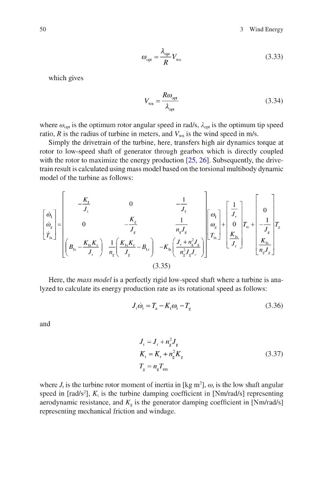
Simply the drivetrain of the turbine, here, transfers high air dynamics torque at
rotor to low-speed shaft of generator through gearbox which is directly coupled
with the rotor to maximize the energy production [25, 26]. Subsequently, the drivetrain result is calculated using mass model based on the torsional multibody dynamic
model of the turbine as follows:
ω
ω
I
g
Ix
l
l
I
g
g
g g
Ix
Ix r
r
T
K
J
J
K
J
n J
B
K K
J
=
−
−
−
−
0
1
0
1
−
−
+
1
1
2
2
n
K K
J
B
K
J n J
n J J
x
g
Ix r
g
Ix
r
g g
g g r
+
ω
ω
I
g
Ix
r
Ix
r
T
J
K
J
1
0
+ −
T
J
K
n J
T
m
g
Ix
g g
g
0
1
(3.35)
Here, the mass model is a perfectly rigid low-speed shaft where a turbine is analyzed to calculate its energy production rate as its rotational speed as follows:
J
T K
T
t t
a
t t
g
ω
ω
= −
−
(3.36)
and
J J n J
K K n K
T n T
t
r
g g
t
r
g g
g
g em
= +
= +
=
2
2
(3.37)
where J t is the turbine rotor moment of inertia in [kg m
2
], ω t is the low shaft angular
speed in [rad/s
2
], K t is the turbine damping coefficient in [Nm/rad/s] representing
aerodynamic resistance, and K g is the generator damping coefficient in [Nm/rad/s]
representing mechanical friction and windage.
3 Wind Energy
ω
λ
opt
opt
wn
= R
V
(3.33)
which gives
V
R
wn
opt
opt
=
ω
λ
(3.34)
where ω opt is the optimum rotor angular speed in rad/s, λ opt is the optimum tip speed
ratio, R is the radius of turbine in meters, and V wn is the wind speed in m/s.
Simply the drivetrain of the turbine, here, transfers high air dynamics torque at
rotor to low-speed shaft of generator through gearbox which is directly coupled
with the rotor to maximize the energy production [25, 26]. Subsequently, the drivetrain result is calculated using mass model based on the torsional multibody dynamic
model of the turbine as follows:
ω
ω
I
g
Ix
l
l
I
g
g
g g
Ix
Ix r
r
T
K
J
J
K
J
n J
B
K K
J
=
−
−
−
−
0
1
0
1
−
−
+
1
1
2
2
n
K K
J
B
K
J n J
n J J
x
g
Ix r
g
Ix
r
g g
g g r
+
ω
ω
I
g
Ix
r
Ix
r
T
J
K
J
1
0
+ −
T
J
K
n J
T
m
g
Ix
g g
g
0
1
(3.35)
Here, the mass model is a perfectly rigid low-speed shaft where a turbine is analyzed to calculate its energy production rate as its rotational speed as follows:
J
T K
T
t t
a
t t
g
ω
ω
= −
−
(3.36)
and
J J n J
K K n K
T n T
t
r
g g
t
r
g g
g
g em
= +
= +
=
2
2
(3.37)
where J t is the turbine rotor moment of inertia in [kg m
2
], ω t is the low shaft angular
speed in [rad/s
2
], K t is the turbine damping coefficient in [Nm/rad/s] representing
aerodynamic resistance, and K g is the generator damping coefficient in [Nm/rad/s]
representing mechanical friction and windage.
3 Wind Energy