

48
I 01 and I 02 are reverse saturation current of diode 1 and diode 2, and V T1 and V T2
are thermal voltage of respective diode. a 1 and a 2 represent the diode ideality
constants.
Simplified model for energy system modeling is thus presented here as
v
V
cKT q
oc
oc
=
/
(3.26)
P
V
cKT q
V
cKT q
V
nKT q
V
V
max
/
ln
/
.
/
=
−
+
+
−
oc
oc
oc
oc
o
0 72
1
1
c c
sc
oc
sc
I
V
G
G
T
T
I
G
G
+
0
0
0
0
0
1 β ln
γ
α
(3.27)
where ν oc is the normalized value of the open-circuit voltage V oc with respect to the
thermal voltage V t = nkT/q, n is the ideality factor (1 < n < 2), K is Boltzmann constant, T is the energy module temperature in kelvin, q is the electron charge, α is the
factor responsible for all the nonlinear effects that the photocurrent depends on, β is
an energy module technology-related dimensionless coefficient, and γ is the factor
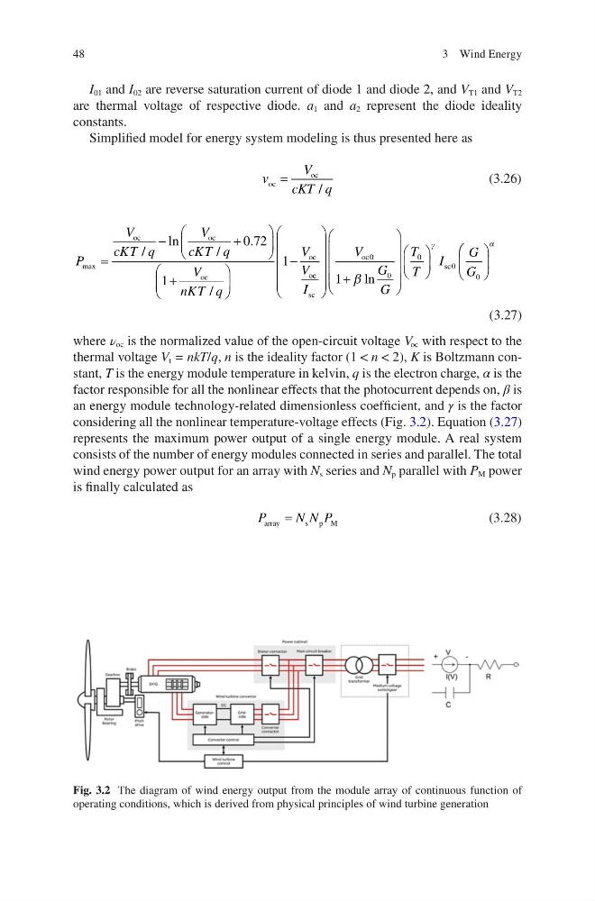
considering all the nonlinear temperature-voltage effects (Fig. 3.2). Equation (3.27)
represents the maximum power output of a single energy module. A real system
consists of the number of energy modules connected in series and parallel. The total
wind energy power output for an array with N s series and N p parallel with P M power
is finally calculated as
P
N N P
array
s p M
=
(3.28)
Fig. 3.2 The diagram of wind energy output from the module array of continuous function of
operating conditions, which is derived from physical principles of wind turbine generation
3 Wind Energy
I 01 and I 02 are reverse saturation current of diode 1 and diode 2, and V T1 and V T2
are thermal voltage of respective diode. a 1 and a 2 represent the diode ideality
constants.
Simplified model for energy system modeling is thus presented here as
v
V
cKT q
oc
oc
=
/
(3.26)
P
V
cKT q
V
cKT q
V
nKT q
V
V
max
/
ln
/
.
/
=
−
+
+
−
oc
oc
oc
oc
o
0 72
1
1
c c
sc
oc
sc
I
V
G
G
T
T
I
G
G
+
0
0
0
0
0
1 β ln
γ
α
(3.27)
where ν oc is the normalized value of the open-circuit voltage V oc with respect to the
thermal voltage V t = nkT/q, n is the ideality factor (1 < n < 2), K is Boltzmann constant, T is the energy module temperature in kelvin, q is the electron charge, α is the
factor responsible for all the nonlinear effects that the photocurrent depends on, β is
an energy module technology-related dimensionless coefficient, and γ is the factor
considering all the nonlinear temperature-voltage effects (Fig. 3.2). Equation (3.27)
represents the maximum power output of a single energy module. A real system
consists of the number of energy modules connected in series and parallel. The total
wind energy power output for an array with N s series and N p parallel with P M power
is finally calculated as
P
N N P
array
s p M
=
(3.28)
Fig. 3.2 The diagram of wind energy output from the module array of continuous function of
operating conditions, which is derived from physical principles of wind turbine generation
3 Wind Energy