

47
I
I
T
T
E
AK T T
rs
rr
r
G
r
=
−
3
1 1
exp
(3.19)
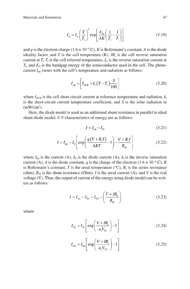
and q is the electron charge (1.6 × 10
−9
C), K is Boltzmann’s constant, A is the diode
ideality factor, and T is the cell temperature (K). IR s is the cell reverse saturation
current at T, T r is the cell referred temperature, I rr is the reverse saturation current at
T r , and E G is the bandgap energy of the semiconductor used in the cell. The photocurrent I ph varies with the cell’s temperature and radiation as follows:
I
I
k T T
S
i
ph
SCR
r
=
+
−
(
)
100
(3.20)
where I SCR is the cell short-circuit current at reference temperature and radiation, k i
is the short-circuit current temperature coefficient, and S is the solar radiation in
(mW/cm
2
).
Here, the diode model is used as an additional shunt resistance in parallel to ideal
shunt diode model. I–V characteristics of energy are as follows:
I I
I
=
−
ph
D
(3.21)
I I
I
q V R I
AKT
V R I
R
=
−
+
(
) −
−
+
ph
s
s
sh
0
1
exp
(3.22)
where I ph is the current (A), I D is the diode current (A), I 0 is the inverse saturation
current (A), A is the diode constant, q is the charge of the electron (1.6 × 10
−9
C), K
is Boltzmann’s constant, T is the areal temperature (°C), R s is the series resistance
(ohm), R sh is the shunt resistance (Ohm), I is the areal current (A), and V is the real
voltage (V). Thus, the output of current of the energy using diode model can be written as follows:
I I
I
I
V IR
R
=
−
−
−
+
pv
D
D
S
sh
1
2
(3.23)
where
I
I
V IR
a V
D
s
T
1
0 1
1
1
1
=
+
−
exp
(3.24)
I
I
V IR
a V
D
s
T
2
0 2
2
2
1
=
+
−
exp
(3.25)
Materials and Simulation
I
I
T
T
E
AK T T
rs
rr
r
G
r
=
−
3
1 1
exp
(3.19)
and q is the electron charge (1.6 × 10
−9
C), K is Boltzmann’s constant, A is the diode
ideality factor, and T is the cell temperature (K). IR s is the cell reverse saturation
current at T, T r is the cell referred temperature, I rr is the reverse saturation current at
T r , and E G is the bandgap energy of the semiconductor used in the cell. The photocurrent I ph varies with the cell’s temperature and radiation as follows:
I
I
k T T
S
i
ph
SCR
r
=
+
−
(
)
100
(3.20)
where I SCR is the cell short-circuit current at reference temperature and radiation, k i
is the short-circuit current temperature coefficient, and S is the solar radiation in
(mW/cm
2
).
Here, the diode model is used as an additional shunt resistance in parallel to ideal
shunt diode model. I–V characteristics of energy are as follows:
I I
I
=
−
ph
D
(3.21)
I I
I
q V R I
AKT
V R I
R
=
−
+
(
) −
−
+
ph
s
s
sh
0
1
exp
(3.22)
where I ph is the current (A), I D is the diode current (A), I 0 is the inverse saturation
current (A), A is the diode constant, q is the charge of the electron (1.6 × 10
−9
C), K
is Boltzmann’s constant, T is the areal temperature (°C), R s is the series resistance
(ohm), R sh is the shunt resistance (Ohm), I is the areal current (A), and V is the real
voltage (V). Thus, the output of current of the energy using diode model can be written as follows:
I I
I
I
V IR
R
=
−
−
−
+
pv
D
D
S
sh
1
2
(3.23)
where
I
I
V IR
a V
D
s
T
1
0 1
1
1
1
=
+
−
exp
(3.24)
I
I
V IR
a V
D
s
T
2
0 2
2
2
1
=
+
−
exp
(3.25)
Materials and Simulation