

373
P v
v v
v v
P v v v
P
v
v v
v v
v v
k
k
k
k
w
C
R
C
R
C
R
R
R
F
C
F
and
( ) =
−
−
⋅
≤ ≤
≤ ≤
≤
≥
0
(17.27)
where P R is the rated power, v C is the cut-in flying train speed, v R is the rated wind
speed, v F is the rated cutout speed, and k is the Weibull shape factor [34, 35]. When
the kinetic energy of the flying train is near to zero, the power coefficient is maximized for an optimal TSR [30] which is calculated as
ω
λ
opt
opt
wn
= R
V
(17.28)
which will give
V
R
wn
opt
opt
=
ω
λ
(17.29)
where ω opt is the optimal speed of flying train in rad/s, λ opt is the optimal tip speed
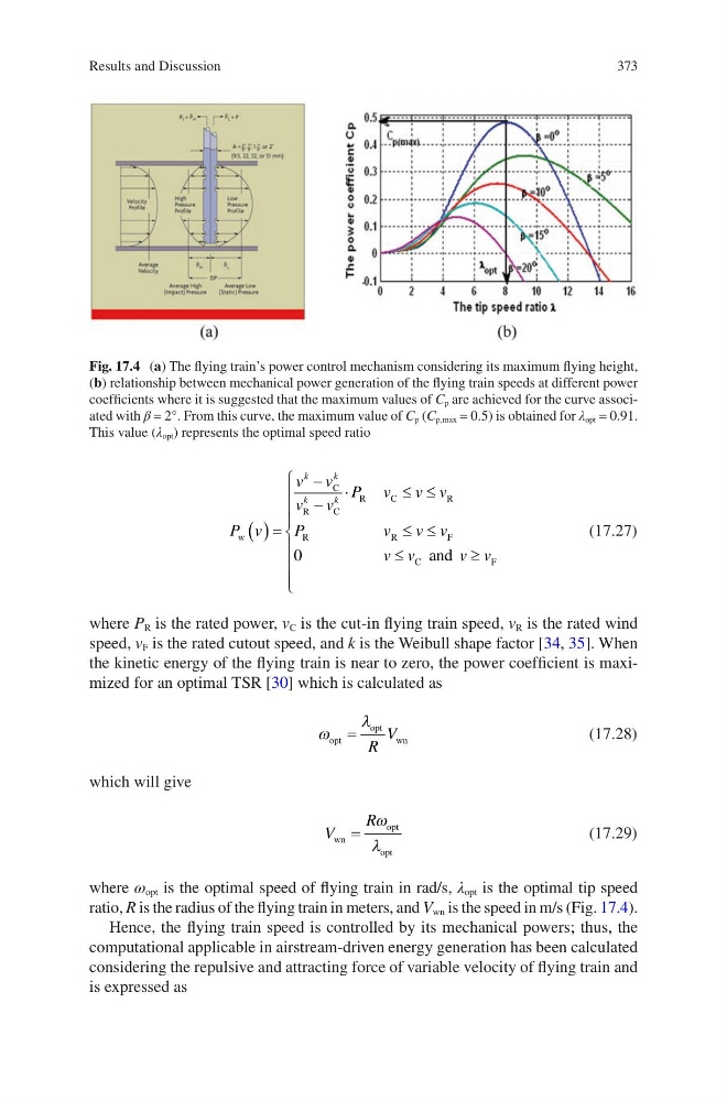
ratio, R is the radius of the flying train in meters, and V wn is the speed in m/s (Fig. 17.4).
Hence, the flying train speed is controlled by its mechanical powers; thus, the
computational applicable in airstream-driven energy generation has been calculated
considering the repulsive and attracting force of variable velocity of flying train and
is expressed as
Fig. 17.4 (a) The flying train’s power control mechanism considering its maximum flying height,
(b) relationship between mechanical power generation of the flying train speeds at different power
coefficients where it is suggested that the maximum values of C p are achieved for the curve associated with β = 2°. From this curve, the maximum value of C p (C p,max = 0.5) is obtained for λ opt = 0.91.
This value (λ opt ) represents the optimal speed ratio
Results and Discussion
P v
v v
v v
P v v v
P
v
v v
v v
v v
k
k
k
k
w
C
R
C
R
C
R
R
R
F
C
F
and
( ) =
−
−
⋅
≤ ≤
≤ ≤
≤
≥
0
(17.27)
where P R is the rated power, v C is the cut-in flying train speed, v R is the rated wind
speed, v F is the rated cutout speed, and k is the Weibull shape factor [34, 35]. When
the kinetic energy of the flying train is near to zero, the power coefficient is maximized for an optimal TSR [30] which is calculated as
ω
λ
opt
opt
wn
= R
V
(17.28)
which will give
V
R
wn
opt
opt
=
ω
λ
(17.29)
where ω opt is the optimal speed of flying train in rad/s, λ opt is the optimal tip speed
ratio, R is the radius of the flying train in meters, and V wn is the speed in m/s (Fig. 17.4).
Hence, the flying train speed is controlled by its mechanical powers; thus, the
computational applicable in airstream-driven energy generation has been calculated
considering the repulsive and attracting force of variable velocity of flying train and
is expressed as
Fig. 17.4 (a) The flying train’s power control mechanism considering its maximum flying height,
(b) relationship between mechanical power generation of the flying train speeds at different power
coefficients where it is suggested that the maximum values of C p are achieved for the curve associated with β = 2°. From this curve, the maximum value of C p (C p,max = 0.5) is obtained for λ opt = 0.91.
This value (λ opt ) represents the optimal speed ratio
Results and Discussion