

207
Conversion of Wind Energy
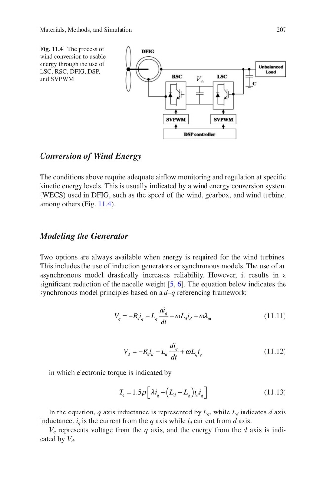
The conditions above require adequate airflow monitoring and regulation at specific
kinetic energy levels. This is usually indicated by a wind energy conversion system
(WECS) used in DFIG, such as the speed of the wind, gearbox, and wind turbine,
among others (Fig. 11.4).
Modeling the Generator
Two options are always available when energy is required for the wind turbines.
This includes the use of induction generators or synchronous models. The use of an
asynchronous model drastically increases reliability. However, it results in a
significant reduction of the nacelle weight [5, 6]. The equation below indicates the
synchronous model principles based on a d–q referencing framework:
V
Ri L
di
dt
L i
q
q
q
q
d d
= −
−
−
+
s
m
ω
ωλ
(11.11)
V
Ri L
di
dt
L i
d
d
d
q
q q
= −
−
+
s
ω
(11.12)
in which electronic torque is indicated by
T
i
L L i i
q
d
q d q
e =
+
−
(
)
1 5
. ρ λ
(11.13)
In the equation, q axis inductance is represented by L q , while L d indicates d axis
inductance. i q is the current from the q axis while i d current from d axis.
V q represents voltage from the q axis, and the energy from the d axis is indicated by V d .
Fig. 11.4 The process of
wind conversion to usable
energy through the use of
LSC, RSC, DFIG, DSP,
and SVPWM
Materials, Methods, and Simulation
Conversion of Wind Energy
The conditions above require adequate airflow monitoring and regulation at specific
kinetic energy levels. This is usually indicated by a wind energy conversion system
(WECS) used in DFIG, such as the speed of the wind, gearbox, and wind turbine,
among others (Fig. 11.4).
Modeling the Generator
Two options are always available when energy is required for the wind turbines.
This includes the use of induction generators or synchronous models. The use of an
asynchronous model drastically increases reliability. However, it results in a
significant reduction of the nacelle weight [5, 6]. The equation below indicates the
synchronous model principles based on a d–q referencing framework:
V
Ri L
di
dt
L i
q
q
q
q
d d
= −
−
−
+
s
m
ω
ωλ
(11.11)
V
Ri L
di
dt
L i
d
d
d
q
q q
= −
−
+
s
ω
(11.12)
in which electronic torque is indicated by
T
i
L L i i
q
d
q d q
e =
+
−
(
)
1 5
. ρ λ
(11.13)
In the equation, q axis inductance is represented by L q , while L d indicates d axis
inductance. i q is the current from the q axis while i d current from d axis.
V q represents voltage from the q axis, and the energy from the d axis is indicated by V d .
Fig. 11.4 The process of
wind conversion to usable
energy through the use of
LSC, RSC, DFIG, DSP,
and SVPWM
Materials, Methods, and Simulation