

206
The primary purpose of altering the angular speed is to enable the extraction of
optimum power levels, a technique commonly known as maximum power point
tracking (MPPT). In scenarios where the blade pitch is at a zero angle, the optimum
TRS is obtained by maximizing the power coefficients:
ω
λ
opt
opt
wn
= R
V
(11.9)
This results in
V
R
wn
opt
opt
=
ω
λ
(11.10)
with
ω opt as the optimum speed of the rotor angle measured in rad/s
λ opt representing the ratio of optimum tip speed
R denoting the turbine radius (m)
V indicating the speed of wind (m/s)
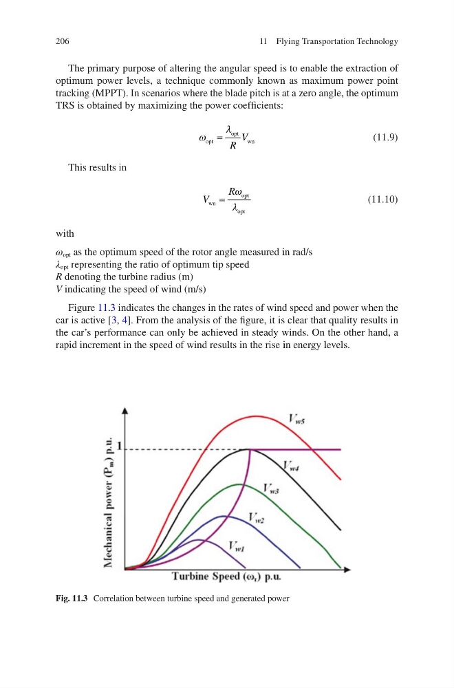
Figure 11.3 indicates the changes in the rates of wind speed and power when the
car is active [3, 4]. From the analysis of the figure, it is clear that quality results in
the car’s performance can only be achieved in steady winds. On the other hand, a
rapid increment in the speed of wind results in the rise in energy levels.
Fig. 11.3 Correlation between turbine speed and generated power
11 Flying Transportation Technology
The primary purpose of altering the angular speed is to enable the extraction of
optimum power levels, a technique commonly known as maximum power point
tracking (MPPT). In scenarios where the blade pitch is at a zero angle, the optimum
TRS is obtained by maximizing the power coefficients:
ω
λ
opt
opt
wn
= R
V
(11.9)
This results in
V
R
wn
opt
opt
=
ω
λ
(11.10)
with
ω opt as the optimum speed of the rotor angle measured in rad/s
λ opt representing the ratio of optimum tip speed
R denoting the turbine radius (m)
V indicating the speed of wind (m/s)
Figure 11.3 indicates the changes in the rates of wind speed and power when the
car is active [3, 4]. From the analysis of the figure, it is clear that quality results in
the car’s performance can only be achieved in steady winds. On the other hand, a
rapid increment in the speed of wind results in the rise in energy levels.
Fig. 11.3 Correlation between turbine speed and generated power
11 Flying Transportation Technology