

204
The equation utilizes second coupled hierarchy formulation to adequately find
the solution to standard k-omega turbulence with shear flow corrections. The numerical solution will, therefore, be considered as an entirely limited volume scheme of
the Reynolds-averaged, Navier–Stokes force compressible that neutralizes the flying car’s total pressure and wall temperatures. To achieve reliable codes that can be
adopted in invalidating the baseline solutions to the flying car’s wing designs 9618
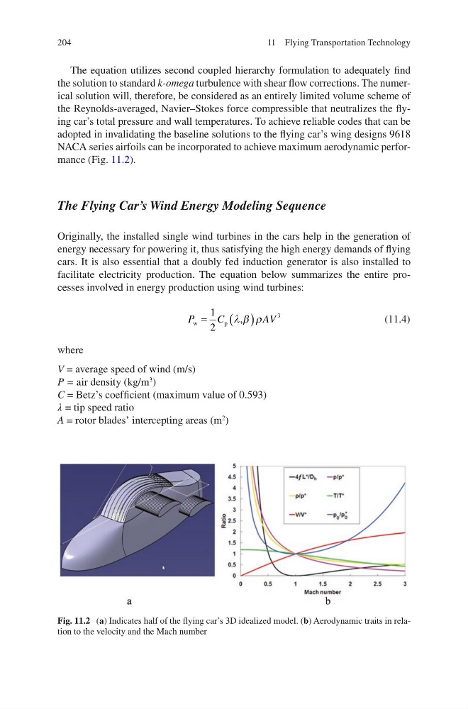
NACA series airfoils can be incorporated to achieve maximum aerodynamic performance (Fig. 11.2).
The Flying Car’s Wind Energy Modeling Sequence
Originally, the installed single wind turbines in the cars help in the generation of
energy necessary for powering it, thus satisfying the high energy demands of flying
cars. It is also essential that a doubly fed induction generator is also installed to
facilitate electricity production. The equation below summarizes the entire processes involved in energy production using wind turbines:
P
C
AV
w
p
,
=
( )
1
2
3
λ β ρ
(11.4)
where
V = average speed of wind (m/s)
P = air density (kg/m
3
)
C = Betz’s coefficient (maximum value of 0.593)
λ = tip speed ratio
A = rotor blades’ intercepting areas (m
2
)
Fig. 11.2 (a) Indicates half of the flying car’s 3D idealized model. (b) Aerodynamic traits in relation to the velocity and the Mach number
11 Flying Transportation Technology
The equation utilizes second coupled hierarchy formulation to adequately find
the solution to standard k-omega turbulence with shear flow corrections. The numerical solution will, therefore, be considered as an entirely limited volume scheme of
the Reynolds-averaged, Navier–Stokes force compressible that neutralizes the flying car’s total pressure and wall temperatures. To achieve reliable codes that can be
adopted in invalidating the baseline solutions to the flying car’s wing designs 9618
NACA series airfoils can be incorporated to achieve maximum aerodynamic performance (Fig. 11.2).
The Flying Car’s Wind Energy Modeling Sequence
Originally, the installed single wind turbines in the cars help in the generation of
energy necessary for powering it, thus satisfying the high energy demands of flying
cars. It is also essential that a doubly fed induction generator is also installed to
facilitate electricity production. The equation below summarizes the entire processes involved in energy production using wind turbines:
P
C
AV
w
p
,
=
( )
1
2
3
λ β ρ
(11.4)
where
V = average speed of wind (m/s)
P = air density (kg/m
3
)
C = Betz’s coefficient (maximum value of 0.593)
λ = tip speed ratio
A = rotor blades’ intercepting areas (m
2
)
Fig. 11.2 (a) Indicates half of the flying car’s 3D idealized model. (b) Aerodynamic traits in relation to the velocity and the Mach number
11 Flying Transportation Technology