

160
EI
,
EI
,
y y j
yy j
u
t
u L t
,
,
0
0
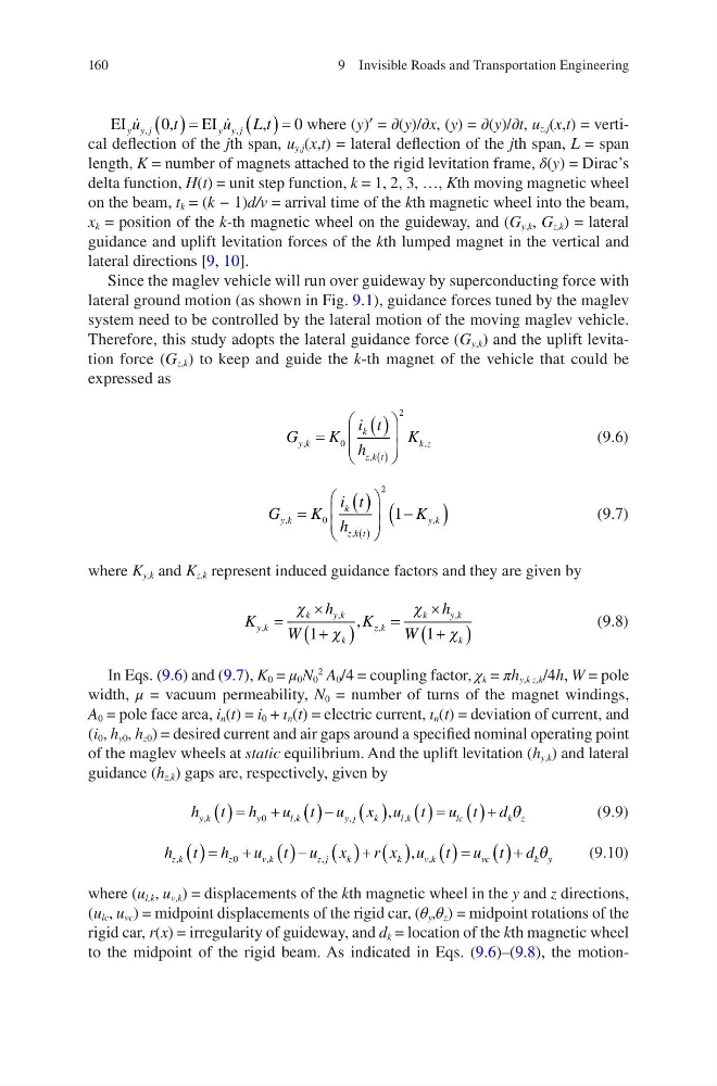
where (y)′ = ∂(y)/∂x, (y) = ∂(y)/∂t, u z,j (x,t) = vertical deflection of the jth span, u y,j (x,t) = lateral deflection of the jth span, L = span
length, K = number of magnets attached to the rigid levitation frame, δ(y) = Dirac’s
delta function, H(t) = unit step function, k = 1, 2, 3, …, Kth moving magnetic wheel
on the beam, t k = (k − 1)d/v = arrival time of the kth magnetic wheel into the beam,
x k = position of the k-th magnetic wheel on the guideway, and (G y,k , G z,k ) = lateral
guidance and uplift levitation forces of the kth lumped magnet in the vertical and
lateral directions [9, 10].
Since the maglev vehicle will run over guideway by superconducting force with
lateral ground motion (as shown in Fig. 9.1), guidance forces tuned by the maglev
system need to be controlled by the lateral motion of the moving maglev vehicle.
Therefore, this study adopts the lateral guidance force (G y,k ) and the uplift levitation force (G z,k ) to keep and guide the k-th magnet of the vehicle that could be
expressed as
G
K
i t
h
K
y k
k
z k t
k z
,
,
,
§
©
¨
¨
·
¹
¸
¸
0
2
(9.6)
G
K
i t
h
K
y k
k
z k t
y k
,
,
,
§
©
¨
¨
·
¹
¸
¸
0
2
1
(9.7)
where K y,k and K z,k represent induced guidance factors and they are given by
K
h
W
K
h
W
y k
k
yk
k
z k
k
yk
k
,
,
,
,
,
u
u
F
F
F
F
1
1
(9.8)
In Eqs. (9.6) and (9.7), K 0 = μ 0 N 0
2
A 0 /4 = coupling factor, χ k = πh y,k z,k /4h, W = pole
width, μ = vacuum permeability, N 0 = number of turns of the magnet windings,
A 0 = pole face area, i n (t) = i 0 + ι n (t) = electric current, ι n (t) = deviation of current, and
(i 0 , h y0 , h z0 ) = desired current and air gaps around a specified nominal operating point
of the maglev wheels at static equilibrium. And the uplift levitation (h y,k ) and lateral
guidance (h z,k ) gaps are, respectively, given by
h t h
u t u x u t u t d
y k
y
lk
y j
k
l k
lc
k z
,
,
,
,
,
0
T
(9.9)
h t h
u t u x
r x u t u t d
z k
z
vk
z j
k
k
vk
v c
k y
,
,
,
,
,
0
T
(9.10)
where (u l,k , u v,k ) = displacements of the kth magnetic wheel in the y and z directions,
(u lc , u vc ) = midpoint displacements of the rigid car, (θ y ,θ z ) = midpoint rotations of the
rigid car, r(x) = irregularity of guideway, and d k = location of the kth magnetic wheel
to the midpoint of the rigid beam. As indicated in Eqs. (9.6)–(9.8), the motion9 Invisible Roads and Transportation Engineering
EI
,
EI
,
y y j
yy j
u
t
u L t
,
,
0
0
where (y)′ = ∂(y)/∂x, (y) = ∂(y)/∂t, u z,j (x,t) = vertical deflection of the jth span, u y,j (x,t) = lateral deflection of the jth span, L = span
length, K = number of magnets attached to the rigid levitation frame, δ(y) = Dirac’s
delta function, H(t) = unit step function, k = 1, 2, 3, …, Kth moving magnetic wheel
on the beam, t k = (k − 1)d/v = arrival time of the kth magnetic wheel into the beam,
x k = position of the k-th magnetic wheel on the guideway, and (G y,k , G z,k ) = lateral
guidance and uplift levitation forces of the kth lumped magnet in the vertical and
lateral directions [9, 10].
Since the maglev vehicle will run over guideway by superconducting force with
lateral ground motion (as shown in Fig. 9.1), guidance forces tuned by the maglev
system need to be controlled by the lateral motion of the moving maglev vehicle.
Therefore, this study adopts the lateral guidance force (G y,k ) and the uplift levitation force (G z,k ) to keep and guide the k-th magnet of the vehicle that could be
expressed as
G
K
i t
h
K
y k
k
z k t
k z
,
,
,
§
©
¨
¨
·
¹
¸
¸
0
2
(9.6)
G
K
i t
h
K
y k
k
z k t
y k
,
,
,
§
©
¨
¨
·
¹
¸
¸
0
2
1
(9.7)
where K y,k and K z,k represent induced guidance factors and they are given by
K
h
W
K
h
W
y k
k
yk
k
z k
k
yk
k
,
,
,
,
,
u
u
F
F
F
F
1
1
(9.8)
In Eqs. (9.6) and (9.7), K 0 = μ 0 N 0
2
A 0 /4 = coupling factor, χ k = πh y,k z,k /4h, W = pole
width, μ = vacuum permeability, N 0 = number of turns of the magnet windings,
A 0 = pole face area, i n (t) = i 0 + ι n (t) = electric current, ι n (t) = deviation of current, and
(i 0 , h y0 , h z0 ) = desired current and air gaps around a specified nominal operating point
of the maglev wheels at static equilibrium. And the uplift levitation (h y,k ) and lateral
guidance (h z,k ) gaps are, respectively, given by
h t h
u t u x u t u t d
y k
y
lk
y j
k
l k
lc
k z
,
,
,
,
,
0
T
(9.9)
h t h
u t u x
r x u t u t d
z k
z
vk
z j
k
k
vk
v c
k y
,
,
,
,
,
0
T
(9.10)
where (u l,k , u v,k ) = displacements of the kth magnetic wheel in the y and z directions,
(u lc , u vc ) = midpoint displacements of the rigid car, (θ y ,θ z ) = midpoint rotations of the
rigid car, r(x) = irregularity of guideway, and d k = location of the kth magnetic wheel
to the midpoint of the rigid beam. As indicated in Eqs. (9.6)–(9.8), the motion9 Invisible Roads and Transportation Engineering