

159
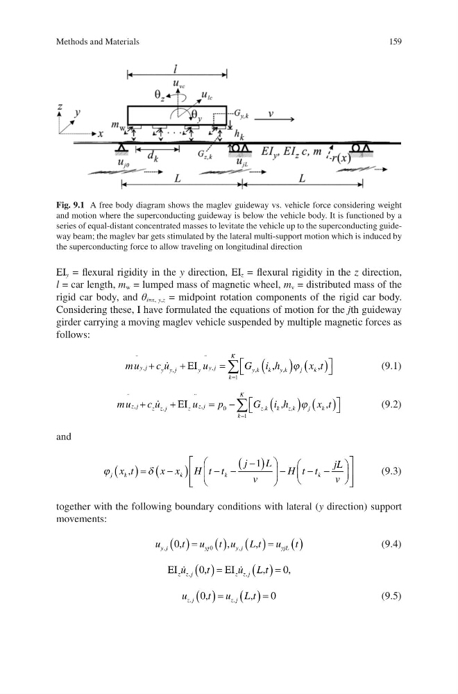
EI y = flexural rigidity in the y direction, EI z = flexural rigidity in the z direction,
l = car length, m w = lumped mass of magnetic wheel, m v = distributed mass of the
rigid car body, and θ i=x, y,z = midpoint rotation components of the rigid car body.
Considering these, I have formulated the equations of motion for the jth guideway
girder carrying a moving maglev vehicle suspended by multiple magnetic forces as
follows:
mu
c u
u
G i h
x t
y j
y y j
y y j
k
K
y k
k yk
j
k
¨
,
,
¨
,
,
,
ª
¬
º
¼
¦
EI
,
,
1
M
(9.1)
mu
c u
u
p
G i h
x t
z j
z z j
z z j
k
K
z k
k zk
j
k
¨
,
,
¨
,
,
,
ª
¬
º
¼
¦
EI
,
,
0
1
M
(9.2)
and
M
G
j
k
k
k
k
x t
x x H t t
j
L
v
H t t
jL
v
,
§
©
¨
·
¹
¸
§
©
¨
·
¹
¸
ª
¬
«
«
º
¼
»
1
» »
(9.3)
together with the following boundary conditions with lateral (y direction) support
movements:
u
t u t u L t u t
y j
yj
y j
yjL
,
,
,
0
0
,
,
(9.4)
EI
,
EI
,
z z j
zz j
u
t
u L t
,
,
,
0
0
u
t u L t
z j
z j
,
,
0
0
,
,
(9.5)
Fig. 9.1 A free body diagram shows the maglev guideway vs. vehicle force considering weight
and motion where the superconducting guideway is below the vehicle body. It is functioned by a
series of equal-distant concentrated masses to levitate the vehicle up to the superconducting guideway beam; the maglev bar gets stimulated by the lateral multi-support motion which is induced by
the superconducting force to allow traveling on longitudinal direction
Methods and Materials
EI y = flexural rigidity in the y direction, EI z = flexural rigidity in the z direction,
l = car length, m w = lumped mass of magnetic wheel, m v = distributed mass of the
rigid car body, and θ i=x, y,z = midpoint rotation components of the rigid car body.
Considering these, I have formulated the equations of motion for the jth guideway
girder carrying a moving maglev vehicle suspended by multiple magnetic forces as
follows:
mu
c u
u
G i h
x t
y j
y y j
y y j
k
K
y k
k yk
j
k
¨
,
,
¨
,
,
,
ª
¬
º
¼
¦
EI
,
,
1
M
(9.1)
mu
c u
u
p
G i h
x t
z j
z z j
z z j
k
K
z k
k zk
j
k
¨
,
,
¨
,
,
,
ª
¬
º
¼
¦
EI
,
,
0
1
M
(9.2)
and
M
G
j
k
k
k
k
x t
x x H t t
j
L
v
H t t
jL
v
,
§
©
¨
·
¹
¸
§
©
¨
·
¹
¸
ª
¬
«
«
º
¼
»
1
» »
(9.3)
together with the following boundary conditions with lateral (y direction) support
movements:
u
t u t u L t u t
y j
yj
y j
yjL
,
,
,
0
0
,
,
(9.4)
EI
,
EI
,
z z j
zz j
u
t
u L t
,
,
,
0
0
u
t u L t
z j
z j
,
,
0
0
,
,
(9.5)
Fig. 9.1 A free body diagram shows the maglev guideway vs. vehicle force considering weight
and motion where the superconducting guideway is below the vehicle body. It is functioned by a
series of equal-distant concentrated masses to levitate the vehicle up to the superconducting guideway beam; the maglev bar gets stimulated by the lateral multi-support motion which is induced by
the superconducting force to allow traveling on longitudinal direction
Methods and Materials