

141
I
I
V IR
a V
D
s
T
1
0 1
1
1
1
=
+
−
exp
(7.26)
I
I
V IR
a V
D
s
T
2
0 1
2
2
1
=
+
−
exp
(7.27)
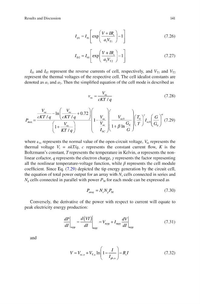
I 01 and I 02 represent the reverse currents of cell, respectively, and V T1 and V T2
represent the thermal voltages of the respective cell. The cell idealist constants are
denoted as a 1 and a 2 . Then the simplified equation of the cell mode is described as
v
V
cKT q
oc
oc
=
/
(7.28)
P
V
cKT q
V
cKT q
V
KT q
V
V
max
/
ln
/
.
/
=
−
+
+
−
oc
oc
oc
oc
oc
0 72
1
1
I I
V
G
G
T
T
I
G
G
SC
oc
sc
+
0
0
0
0
0
1 β ln
γ
α
(7.29)
where ν oc represents the normal value of the open-circuit voltage, V oc represents the
thermal voltage V t = nkT/q, c represents the constant current flow, K is the
Boltzmann’s constant, T represents the temperature in Kelvin, α represents the nonlinear cofactor, q represents the electron charge, γ represents the factor representing
all the nonlinear temperature-voltage function, while β represents the cell module
coefficient. Since Eq. (7.29) depicted the tip energy generation by the circuit cell,
the equation of total power output for an array with N s cells connected in series and
N p cells connected in parallel with power P M for each mode can be expressed as
P
N N P
array
s p M
=
(7.30)
Conversely, the derivative of the power with respect to current will equate to
peak electricity energy production:
dP
dI
d VI
dI
V
I
dV
dI
mpp
mpp
mpp
m pp
mpp
=
( ) =
+
(7.31)
and
V V
V
I
I
R I
n
n
=
+
−
−
oc
T
ph n
s
,
,
,
ln 1
(7.32)
Results and Discussion
I
I
V IR
a V
D
s
T
1
0 1
1
1
1
=
+
−
exp
(7.26)
I
I
V IR
a V
D
s
T
2
0 1
2
2
1
=
+
−
exp
(7.27)
I 01 and I 02 represent the reverse currents of cell, respectively, and V T1 and V T2
represent the thermal voltages of the respective cell. The cell idealist constants are
denoted as a 1 and a 2 . Then the simplified equation of the cell mode is described as
v
V
cKT q
oc
oc
=
/
(7.28)
P
V
cKT q
V
cKT q
V
KT q
V
V
max
/
ln
/
.
/
=
−
+
+
−
oc
oc
oc
oc
oc
0 72
1
1
I I
V
G
G
T
T
I
G
G
SC
oc
sc
+
0
0
0
0
0
1 β ln
γ
α
(7.29)
where ν oc represents the normal value of the open-circuit voltage, V oc represents the
thermal voltage V t = nkT/q, c represents the constant current flow, K is the
Boltzmann’s constant, T represents the temperature in Kelvin, α represents the nonlinear cofactor, q represents the electron charge, γ represents the factor representing
all the nonlinear temperature-voltage function, while β represents the cell module
coefficient. Since Eq. (7.29) depicted the tip energy generation by the circuit cell,
the equation of total power output for an array with N s cells connected in series and
N p cells connected in parallel with power P M for each mode can be expressed as
P
N N P
array
s p M
=
(7.30)
Conversely, the derivative of the power with respect to current will equate to
peak electricity energy production:
dP
dI
d VI
dI
V
I
dV
dI
mpp
mpp
mpp
m pp
mpp
=
( ) =
+
(7.31)
and
V V
V
I
I
R I
n
n
=
+
−
−
oc
T
ph n
s
,
,
,
ln 1
(7.32)
Results and Discussion