

184
7 Nano-Mechanical Properties of Solid Surfaces Obtained …
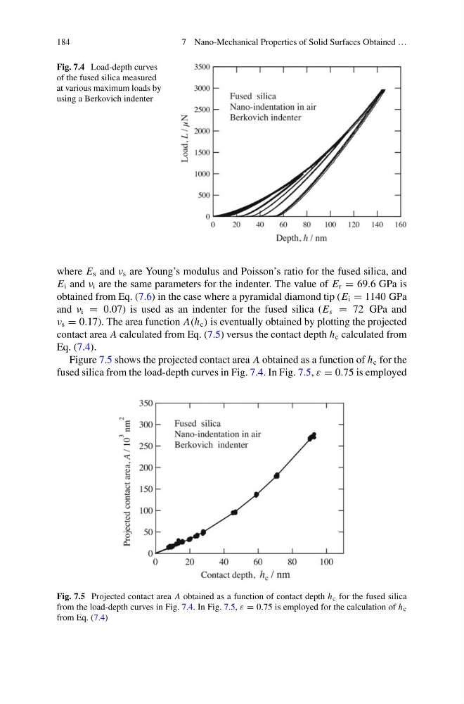
Fig. 7.4 Load-depth curves
of the fused silica measured
at various maximum loads by
using a Berkovich indenter
where E s and ν s are Young’s modulus and Poisson’s ratio for the fused silica, and
E i and ν i are the same parameters for the indenter. The value of E r = 69.6 GPa is
obtained from Eq. (7.6) in the case where a pyramidal diamond tip (E i = 1140 GPa
and ν i = 0.07) is used as an indenter for the fused silica (E s = 72 GPa and
ν s = 0.17). The area function A(h c ) is eventually obtained by plotting the projected
contact area A calculated from Eq. (7.5) versus the contact depth h c calculated from
Eq. (7.4).
Figure 7.5 shows the projected contact area A obtained as a function of h c for the
fused silica from the load-depth curves in Fig. 7.4. In Fig. 7.5, ε = 0.75 is employed
Fig. 7.5 Projected contact area A obtained as a function of contact depth h c for the fused silica
from the load-depth curves in Fig. 7.4. In Fig. 7.5, ε = 0.75 is employed for the calculation of h c
from Eq. (7.4)
7 Nano-Mechanical Properties of Solid Surfaces Obtained …
Fig. 7.4 Load-depth curves
of the fused silica measured
at various maximum loads by
using a Berkovich indenter
where E s and ν s are Young’s modulus and Poisson’s ratio for the fused silica, and
E i and ν i are the same parameters for the indenter. The value of E r = 69.6 GPa is
obtained from Eq. (7.6) in the case where a pyramidal diamond tip (E i = 1140 GPa
and ν i = 0.07) is used as an indenter for the fused silica (E s = 72 GPa and
ν s = 0.17). The area function A(h c ) is eventually obtained by plotting the projected
contact area A calculated from Eq. (7.5) versus the contact depth h c calculated from
Eq. (7.4).
Figure 7.5 shows the projected contact area A obtained as a function of h c for the
fused silica from the load-depth curves in Fig. 7.4. In Fig. 7.5, ε = 0.75 is employed
Fig. 7.5 Projected contact area A obtained as a function of contact depth h c for the fused silica
from the load-depth curves in Fig. 7.4. In Fig. 7.5, ε = 0.75 is employed for the calculation of h c
from Eq. (7.4)