

7.2 Fundamentals of Nano-Indentation
181
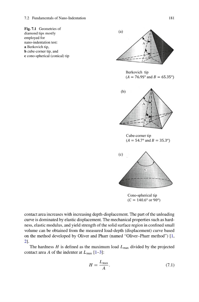
Fig. 7.1 Geometries of
diamond tips mostly
employed for
nano-indentation test:
a Berkovich tip,
b cube-corner tip, and
c cono-spherical (conical) tip
contact area increases with increasing depth-displacement. The part of the unloading
curve is dominated by elastic displacement. The mechanical properties such as hardness, elastic modulus, and yield strength of the solid surface region in confined small
volume can be obtained from the measured load-depth (displacement) curve based
on the method developed by Oliver and Pharr (named “Oliver–Pharr method”) [1,
2].
The hardness H is defined as the maximum load L max divided by the projected
contact area A of the indenter at L max [1–3]:
H =
L max
A
.
(7.1)
181
Fig. 7.1 Geometries of
diamond tips mostly
employed for
nano-indentation test:
a Berkovich tip,
b cube-corner tip, and
c cono-spherical (conical) tip
contact area increases with increasing depth-displacement. The part of the unloading
curve is dominated by elastic displacement. The mechanical properties such as hardness, elastic modulus, and yield strength of the solid surface region in confined small
volume can be obtained from the measured load-depth (displacement) curve based
on the method developed by Oliver and Pharr (named “Oliver–Pharr method”) [1,
2].
The hardness H is defined as the maximum load L max divided by the projected
contact area A of the indenter at L max [1–3]:
H =
L max
A
.
(7.1)