

4.1 Sandwich core
39
4.1.2 Experimental analysis
All experiments were conducted on honeycomb core specimens, which were cut directly
from a cured sandwich panel comprising the investigated core and bonded glass fiber
fabric reinforced phenolic resin skins. The skins consisted of prepregs complying with the
Airbus standards ABS5047-02 and ABS5047-08 [Air15]. The nominal thickness of the
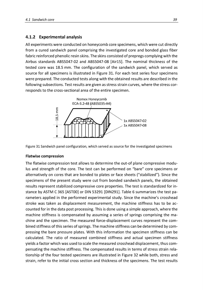
tested core was 18.5 mm. The configuration of the sandwich panel, which served as
source for all specimens is illustrated in Figure 31. For each test series four specimens
were prepared. The conducted tests along with the obtained results are described in the
following subsections. Test results are given as stress strain curves, where the stress corresponds to the cross-sectional area of the entire specimen.
Figure 31 Sandwich panel configuration, which served as source for the investigated specimens
Flatwise compression
The flatwise compression test allows to determine the out-of plane compressive modulus and strength of the core. The test can be performed on “bare” core specimens or
alternatively on cores that are bonded to plates or face sheets (“stabilized”). Since the
specimens of the present study were cut from bonded sandwich panels, the obtained
results represent stabilized compressive core properties. The test is standardized for instance by ASTM C 365 [AST00] or DIN 53291 [DIN291]. Table 6 summarizes the test parameters applied in the performed experimental study. Since the machine’s crosshead
stroke was taken as displacement measurement, the machine stiffness has to be accounted for in the data post processing. This is done using a simple approach, where the
machine stiffness is compensated by assuming a series of springs comprising the machine and the specimen. The measured force-displacement curves represent the combined stiffness of this series of springs. The machine stiffness can be determined by compressing the bare pressure plates. With this information the specimen stiffness can be
calculated. The ratio of measured combined stiffness and actual specimen stiffness
yields a factor which was used to scale the measured crosshead displacement, thus compensating the machine stiffness. The compensated results in terms of stress strain relationship of the four tested specimens are illustrated in Figure 32 while both, stress and
strain, refer to the initial cross section and thickness of the specimens. The test results
39
4.1.2 Experimental analysis
All experiments were conducted on honeycomb core specimens, which were cut directly
from a cured sandwich panel comprising the investigated core and bonded glass fiber
fabric reinforced phenolic resin skins. The skins consisted of prepregs complying with the
Airbus standards ABS5047-02 and ABS5047-08 [Air15]. The nominal thickness of the
tested core was 18.5 mm. The configuration of the sandwich panel, which served as
source for all specimens is illustrated in Figure 31. For each test series four specimens
were prepared. The conducted tests along with the obtained results are described in the
following subsections. Test results are given as stress strain curves, where the stress corresponds to the cross-sectional area of the entire specimen.
Figure 31 Sandwich panel configuration, which served as source for the investigated specimens
Flatwise compression
The flatwise compression test allows to determine the out-of plane compressive modulus and strength of the core. The test can be performed on “bare” core specimens or
alternatively on cores that are bonded to plates or face sheets (“stabilized”). Since the
specimens of the present study were cut from bonded sandwich panels, the obtained
results represent stabilized compressive core properties. The test is standardized for instance by ASTM C 365 [AST00] or DIN 53291 [DIN291]. Table 6 summarizes the test parameters applied in the performed experimental study. Since the machine’s crosshead
stroke was taken as displacement measurement, the machine stiffness has to be accounted for in the data post processing. This is done using a simple approach, where the
machine stiffness is compensated by assuming a series of springs comprising the machine and the specimen. The measured force-displacement curves represent the combined stiffness of this series of springs. The machine stiffness can be determined by compressing the bare pressure plates. With this information the specimen stiffness can be
calculated. The ratio of measured combined stiffness and actual specimen stiffness
yields a factor which was used to scale the measured crosshead displacement, thus compensating the machine stiffness. The compensated results in terms of stress strain relationship of the four tested specimens are illustrated in Figure 32 while both, stress and
strain, refer to the initial cross section and thickness of the specimens. The test results