

124
7 Virtual testing approach for sandwich panel joints
require a multitude of variations of the implemented FE-model. This is aided by the derived parametric FE-model as illustrated in Figure 90.
The second step concludes with a FE-model, which remodels the performed structural
tests and qualitatively reproduces the occurring damage mechanisms and the recorded
curve progression. The implemented model is optimized for computational effort and
relevant numerical parameters have been demonstrated to converge.
Model calibration and verification
With an adequate FE-model implemented, the last step is the calibration of the model
using the experimental results of the first step. Cox [Cox08] recommends that this task
should be carried out using a formal approach like inverse problem methods. Such a
model-based approach enables to quantify the degree to which a model parameter can
be determined. Inverse problem methods are for instance described by Aster et al.
[Ast13] and Tarantola [Tar04]. However, Cox also pointed out that these methods are
difficult to implement for complex non-linear experiments. Inverse problems can also be
solved using simpler methods such as curve fitting by minimizing the deviance between
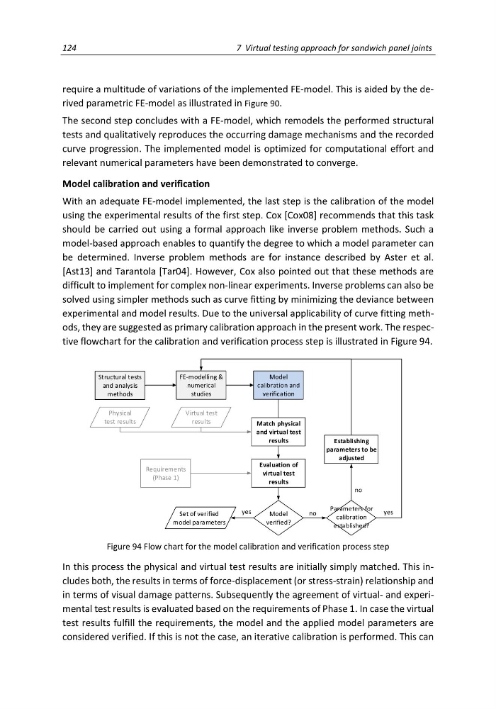
experimental and model results. Due to the universal applicability of curve fitting methods, they are suggested as primary calibration approach in the present work. The respective flowchart for the calibration and verification process step is illustrated in Figure 94.
Structural tests
and analysis
methods
FE-modelling &
numerical
studies
Model
calibration and
verification
Match physical
and virtual test
results
Model
verified?
Physical
test results
Establishing
parameters to be
adjusted
no
yes
Set of verified
model parameters
Evaluation of
virtual test
results
Parameters for
calibration
established?
yes
no
Requirements
(Phase 1)
Virtual test
results
Figure 94 Flow chart for the model calibration and verification process step
In this process the physical and virtual test results are initially simply matched. This includes both, the results in terms of force-displacement (or stress-strain) relationship and
in terms of visual damage patterns. Subsequently the agreement of virtual- and experimental test results is evaluated based on the requirements of Phase 1. In case the virtual
test results fulfill the requirements, the model and the applied model parameters are
considered verified. If this is not the case, an iterative calibration is performed. This can
7 Virtual testing approach for sandwich panel joints
require a multitude of variations of the implemented FE-model. This is aided by the derived parametric FE-model as illustrated in Figure 90.
The second step concludes with a FE-model, which remodels the performed structural
tests and qualitatively reproduces the occurring damage mechanisms and the recorded
curve progression. The implemented model is optimized for computational effort and
relevant numerical parameters have been demonstrated to converge.
Model calibration and verification
With an adequate FE-model implemented, the last step is the calibration of the model
using the experimental results of the first step. Cox [Cox08] recommends that this task
should be carried out using a formal approach like inverse problem methods. Such a
model-based approach enables to quantify the degree to which a model parameter can
be determined. Inverse problem methods are for instance described by Aster et al.
[Ast13] and Tarantola [Tar04]. However, Cox also pointed out that these methods are
difficult to implement for complex non-linear experiments. Inverse problems can also be
solved using simpler methods such as curve fitting by minimizing the deviance between
experimental and model results. Due to the universal applicability of curve fitting methods, they are suggested as primary calibration approach in the present work. The respective flowchart for the calibration and verification process step is illustrated in Figure 94.
Structural tests
and analysis
methods
FE-modelling &
numerical
studies
Model
calibration and
verification
Match physical
and virtual test
results
Model
verified?
Physical
test results
Establishing
parameters to be
adjusted
no
yes
Set of verified
model parameters
Evaluation of
virtual test
results
Parameters for
calibration
established?
yes
no
Requirements
(Phase 1)
Virtual test
results
Figure 94 Flow chart for the model calibration and verification process step
In this process the physical and virtual test results are initially simply matched. This includes both, the results in terms of force-displacement (or stress-strain) relationship and
in terms of visual damage patterns. Subsequently the agreement of virtual- and experimental test results is evaluated based on the requirements of Phase 1. In case the virtual
test results fulfill the requirements, the model and the applied model parameters are
considered verified. If this is not the case, an iterative calibration is performed. This can