

5.2 In-plane shear
89
The symmetry of the specimen and loading condition is utilized by implementing a quarter model in order to reduce computational time. The steel fixture is modelled using
beam elements (B21) with an equivalent cross section as the actual rails.
b)
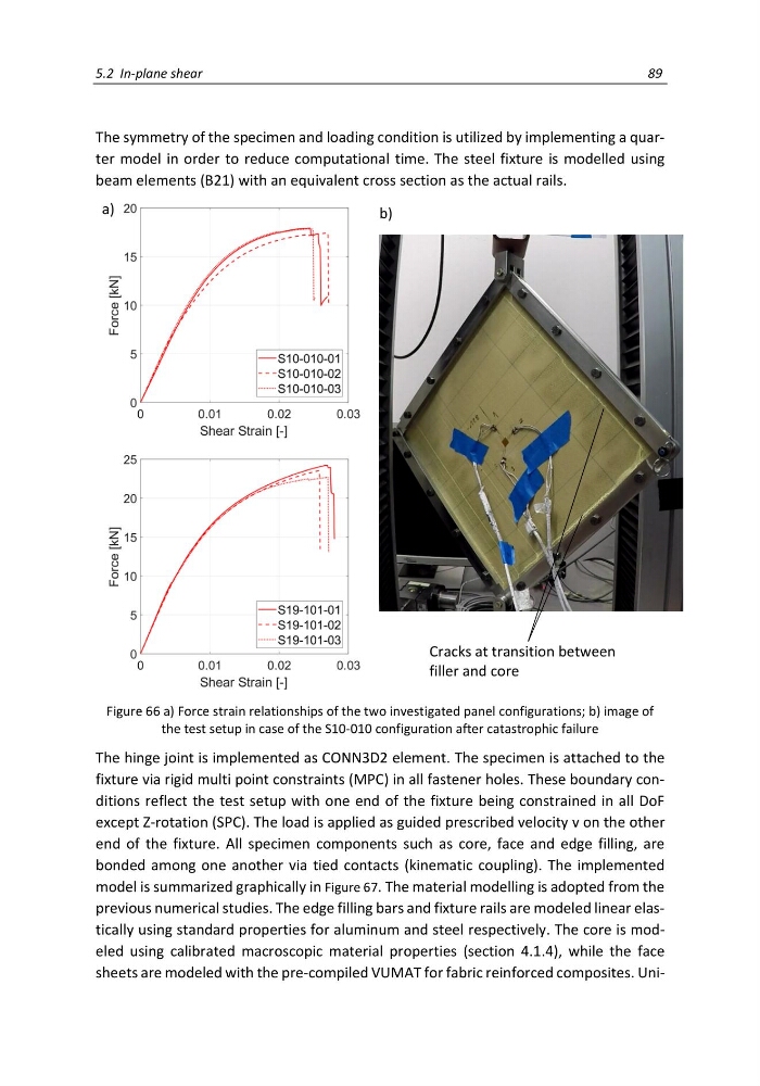
Figure 66 a) Force strain relationships of the two investigated panel configurations; b) image of
the test setup in case of the S10-010 configuration after catastrophic failure
The hinge joint is implemented as CONN3D2 element. The specimen is attached to the
fixture via rigid multi point constraints (MPC) in all fastener holes. These boundary conditions reflect the test setup with one end of the fixture being constrained in all DoF
except Z-rotation (SPC). The load is applied as guided prescribed velocity v on the other
end of the fixture. All specimen components such as core, face and edge filling, are
bonded among one another via tied contacts (kinematic coupling). The implemented
model is summarized graphically in Figure 67. The material modelling is adopted from the
previous numerical studies. The edge filling bars and fixture rails are modeled linear elastically using standard properties for aluminum and steel respectively. The core is modeled using calibrated macroscopic material properties (section 4.1.4), while the face
sheets are modeled with the pre-compiled VUMAT for fabric reinforced composites. UniCracks at transition between
filler and core
a)
89
The symmetry of the specimen and loading condition is utilized by implementing a quarter model in order to reduce computational time. The steel fixture is modelled using
beam elements (B21) with an equivalent cross section as the actual rails.
b)
Figure 66 a) Force strain relationships of the two investigated panel configurations; b) image of
the test setup in case of the S10-010 configuration after catastrophic failure
The hinge joint is implemented as CONN3D2 element. The specimen is attached to the
fixture via rigid multi point constraints (MPC) in all fastener holes. These boundary conditions reflect the test setup with one end of the fixture being constrained in all DoF
except Z-rotation (SPC). The load is applied as guided prescribed velocity v on the other
end of the fixture. All specimen components such as core, face and edge filling, are
bonded among one another via tied contacts (kinematic coupling). The implemented
model is summarized graphically in Figure 67. The material modelling is adopted from the
previous numerical studies. The edge filling bars and fixture rails are modeled linear elastically using standard properties for aluminum and steel respectively. The core is modeled using calibrated macroscopic material properties (section 4.1.4), while the face
sheets are modeled with the pre-compiled VUMAT for fabric reinforced composites. UniCracks at transition between
filler and core
a)