

408
L. Paj˛ ak et al.
~G
power 440 MWel, working power 220 MWel.
Efficiency of thermal energy conversion into electricity*:
- winter half-year 41,18%,
- summer half-year 35,01%,
- annual average 38,09%.
Gross electricity production*:
- 753 GWh/winter half-year (average power 172 MWel),
- 622 GWh/summer half-year (average power 142 MWel),
- 1375 GWh/year (average power 157 MWel).
Power of condensers
(cooling)
@ :
- winter half-year 178 MW,
- summer half-year 179 MW,
- annual average 179 MW.
Power of boilers delivered in
fuel
@ :
- winter half-year 418 MW,
- summer half-year 511 MW
- annual average 412 MW
Stream and average annual temperature of
cooling water, before the power plant *:
- winter half-year 8,0 m
3
/s; 6,5°C,
- summer half-year 6,9 m
3 /s; 17,1°C,
- annual average 7,4 m
3
/s; 11,8°C.
Stream and average annual
temperature of cooling water, behind
the power plant*:
- winter hal-year 8,0 m
3
/s; 11,8°C,
- summer half-year 6,9 m
3 /s; 23,3°C,
- annual average 7,4 m
3
/s; 17,6°C.
technological steam*: 535°C; 9,0 MPa
Energetic canal
Data sources:
* - from power plant's monitoring database,
@ - values determined by calculation on the basis of archived data from power plant
1
2
3
4
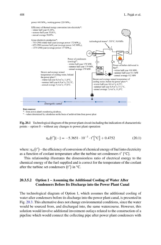
Fig. 20.1 Technological diagram of the power plant circuit including the indication of characteristic
points – option 0 – without any changes to power plant operation
η el
t
[−] = −5.3651 · 10
−3
· t
◦ C
+ 0.4752
(20.1)
where: η el
t
– the efficiency of conversion of chemical energy of fuel into electricity
as a function of coolant temperature after the turbine set condensers t
[°C].
This relationship illustrates the dimensionless ratio of electrical energy to the
chemical energy of the fuel supplied and is correct for the temperature of the coolant
after the turbine set condensers
t
in °C.
20.3.5.2 Option 1 – Assuming the Additional Cooling of Water After
Condensers Before Its Discharge into the Power Plant Canal
The technological diagram of Option 1, which assumes the additional cooling of
water after condensers before its discharge into the power plant canal, is presented in
Fig. 20.3. This alternative does not change environmental conditions, since the water
would be sourced from, and discharged into, the same watercourse. However, this
solution would involve additional investment outlays related to the construction of a
pipeline which would connect the collecting pipe after power plant condensers with
L. Paj˛ ak et al.
~G
power 440 MWel, working power 220 MWel.
Efficiency of thermal energy conversion into electricity*:
- winter half-year 41,18%,
- summer half-year 35,01%,
- annual average 38,09%.
Gross electricity production*:
- 753 GWh/winter half-year (average power 172 MWel),
- 622 GWh/summer half-year (average power 142 MWel),
- 1375 GWh/year (average power 157 MWel).
Power of condensers
(cooling)
@ :
- winter half-year 178 MW,
- summer half-year 179 MW,
- annual average 179 MW.
Power of boilers delivered in
fuel
@ :
- winter half-year 418 MW,
- summer half-year 511 MW
- annual average 412 MW
Stream and average annual temperature of
cooling water, before the power plant *:
- winter half-year 8,0 m
3
/s; 6,5°C,
- summer half-year 6,9 m
3 /s; 17,1°C,
- annual average 7,4 m
3
/s; 11,8°C.
Stream and average annual
temperature of cooling water, behind
the power plant*:
- winter hal-year 8,0 m
3
/s; 11,8°C,
- summer half-year 6,9 m
3 /s; 23,3°C,
- annual average 7,4 m
3
/s; 17,6°C.
technological steam*: 535°C; 9,0 MPa
Energetic canal
Data sources:
* - from power plant's monitoring database,
@ - values determined by calculation on the basis of archived data from power plant
1
2
3
4
Fig. 20.1 Technological diagram of the power plant circuit including the indication of characteristic
points – option 0 – without any changes to power plant operation
η el
t
[−] = −5.3651 · 10
−3
· t
◦ C
+ 0.4752
(20.1)
where: η el
t
– the efficiency of conversion of chemical energy of fuel into electricity
as a function of coolant temperature after the turbine set condensers t
[°C].
This relationship illustrates the dimensionless ratio of electrical energy to the
chemical energy of the fuel supplied and is correct for the temperature of the coolant
after the turbine set condensers
t
in °C.
20.3.5.2 Option 1 – Assuming the Additional Cooling of Water After
Condensers Before Its Discharge into the Power Plant Canal
The technological diagram of Option 1, which assumes the additional cooling of
water after condensers before its discharge into the power plant canal, is presented in
Fig. 20.3. This alternative does not change environmental conditions, since the water
would be sourced from, and discharged into, the same watercourse. However, this
solution would involve additional investment outlays related to the construction of a
pipeline which would connect the collecting pipe after power plant condensers with