

70
surface area, pore volume, and acidity to selectively crack heavier hydrocarbons
into gasoline range molecules. Zeolite catalyst was first commercially manufactured by Grace Davison and Filtrol. Zeolite structure inherently is not stable in the
high steam partial pressure environment of an FCC unit [28]. Its stability was
improved by dealuminating the zeolite by consecutive steaming, washing, and
leaching cycles. This dealuminated zeolite was called ultra-stable Y or simply
US-Y. Another widely practiced method studied in the 1980s is to improve the zeolite’s stability by ion exchange of aluminum counter-ions with rare-earth ions. Such
ion-exchanged zeolites are called RE-Y (Fig. 4). These stabilized zeolites, however,
reduced gasoline octane by catalyzing bimolecular hydrogen transfer reactions [29].
This new generation of catalysts led to fundamental alterations to the design and
operation of FCC units. Since they had high selectivity and activity, it was observed
that at the existing contact time in FCC reactors, a copious amount of coke was
formed, which caused lower yield and heat balance issues. This led to the conclusion that much shorter residence time was required to maintain the selectivity
toward desired products. Hence, fluidized bed cracking was substituted by riser
cracking. Any and all configurations post-1964 incorporated the riser cracking
design (Fig. 5).
Further developments in this field were motivated by either a desire to upgrade
resid feed in the FCC or to maximize propylene yield for petrochemical manufacture. Design improvements on the conventional FCC design were made to incorporate the high coke yielding resid feed, the higher catalyst to oil ratio required, higher
capacity of the wet gas compressor, better metallurgy, efficient cyclones, better feed
nozzles, catalyst cooling, etc. Technologies such as deep catalytic cracking (DCC),
petro FCC, resid FCC, etc. emerged. A catalyst that can withstand the high concentration of metal impurities in resid feed was developed. A new zeolite with
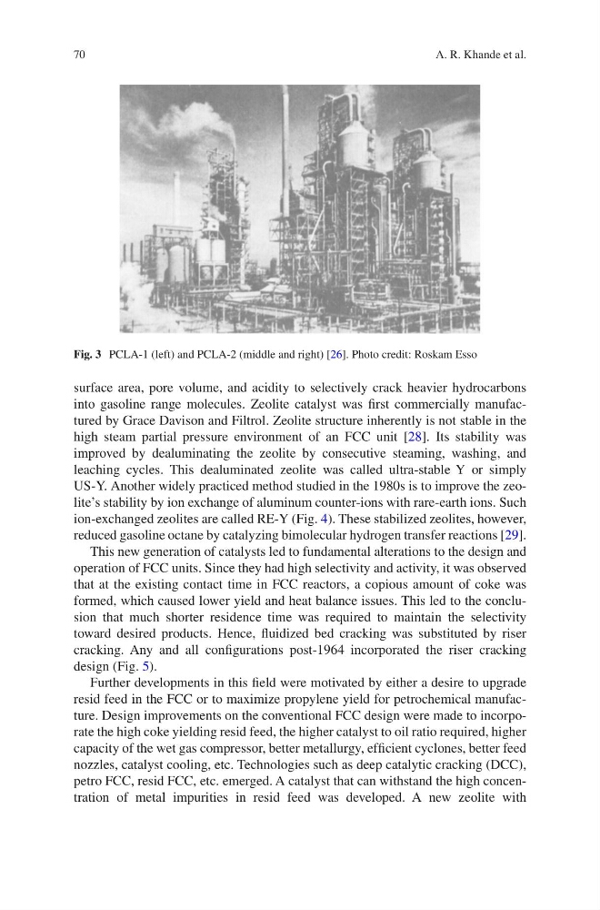
Fig. 3 PCLA-1 (left) and PCLA-2 (middle and right) [26]. Photo credit: Roskam Esso
A. R. Khande et al.
surface area, pore volume, and acidity to selectively crack heavier hydrocarbons
into gasoline range molecules. Zeolite catalyst was first commercially manufactured by Grace Davison and Filtrol. Zeolite structure inherently is not stable in the
high steam partial pressure environment of an FCC unit [28]. Its stability was
improved by dealuminating the zeolite by consecutive steaming, washing, and
leaching cycles. This dealuminated zeolite was called ultra-stable Y or simply
US-Y. Another widely practiced method studied in the 1980s is to improve the zeolite’s stability by ion exchange of aluminum counter-ions with rare-earth ions. Such
ion-exchanged zeolites are called RE-Y (Fig. 4). These stabilized zeolites, however,
reduced gasoline octane by catalyzing bimolecular hydrogen transfer reactions [29].
This new generation of catalysts led to fundamental alterations to the design and
operation of FCC units. Since they had high selectivity and activity, it was observed
that at the existing contact time in FCC reactors, a copious amount of coke was
formed, which caused lower yield and heat balance issues. This led to the conclusion that much shorter residence time was required to maintain the selectivity
toward desired products. Hence, fluidized bed cracking was substituted by riser
cracking. Any and all configurations post-1964 incorporated the riser cracking
design (Fig. 5).
Further developments in this field were motivated by either a desire to upgrade
resid feed in the FCC or to maximize propylene yield for petrochemical manufacture. Design improvements on the conventional FCC design were made to incorporate the high coke yielding resid feed, the higher catalyst to oil ratio required, higher
capacity of the wet gas compressor, better metallurgy, efficient cyclones, better feed
nozzles, catalyst cooling, etc. Technologies such as deep catalytic cracking (DCC),
petro FCC, resid FCC, etc. emerged. A catalyst that can withstand the high concentration of metal impurities in resid feed was developed. A new zeolite with
Fig. 3 PCLA-1 (left) and PCLA-2 (middle and right) [26]. Photo credit: Roskam Esso
A. R. Khande et al.