

542
hydrocarbon, hydrogen and/ halide flames where combustion, decomposition or
hydrolysis of the precursor takes place to produce the catalytic component in the gas
phase and subsequent catalyst particle formation is by the gas to particle conversion
route. In the liquid-fed flame synthesis, precursor liquid is first aerosolized to form
fine liquid droplets and then introduced into the flame. Depending on whether sufficient energy is available in the flame for complete evaporation of the precursor,
catalyst particle formation can be either through the gas to particle conversion route
or the droplet to particle conversion route [49, 52, 61].
The liquid-fed flame synthesis is divided into flame spray pyrolysis (FSP) and
flame-assisted spray pyrolysis (FASP) depending on whether the liquid precursor
solution drives the combustion process. In flame spray pyrolysis the precursor is
dissolved in a combustible solvent and therefore drives the combustion process [49,
52, 61]. Figure 4 shows different flame aerosol reactors (burner set-up) used in
flame synthesis. The coflow diffusion flame and the flame spray pyrolysis aerosol
reactors are easily scalable to industrial scales while the others are limited to laboratory scale. The coflow diffusion flame aerosol reactor is typically used for vapourfed flame synthesis while the flame spray pyrolysis is used for liquid-fed flame
synthesis.
In the flame spary pyrolysis burner, the liquid precursor mixture is delivered
through the central capillary tube. Oxygen or air used as the dispersion gas is introduced at the annular region around capillary, and it serves to break up the liquid
precursor mixture into micron size droplets. The sprayed droplets are ignited by
methane flamelets which serve as pilot flames for stabilizing combustion. In the
coflow diffusion flame aerosol reactor, the vapourized precursor is introduced at the
central nozzle while the oxidant (typically O 2 or air) and fuel are introduced in the
annular regions as shown in Fig. 3a. In aerosol reactors, the synthesized catalyst
morphology and catalytic properties are determined by the residence time of the
catalyst particles in the flame and the temperature profile of the flame.
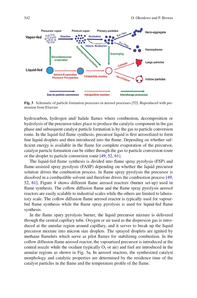
Fig. 3 Schematic of particle formation processes in aerosol processes [52]. Reproduced with permission from Elsevier
O. Okonkwo and P. Biswas
hydrocarbon, hydrogen and/ halide flames where combustion, decomposition or
hydrolysis of the precursor takes place to produce the catalytic component in the gas
phase and subsequent catalyst particle formation is by the gas to particle conversion
route. In the liquid-fed flame synthesis, precursor liquid is first aerosolized to form
fine liquid droplets and then introduced into the flame. Depending on whether sufficient energy is available in the flame for complete evaporation of the precursor,
catalyst particle formation can be either through the gas to particle conversion route
or the droplet to particle conversion route [49, 52, 61].
The liquid-fed flame synthesis is divided into flame spray pyrolysis (FSP) and
flame-assisted spray pyrolysis (FASP) depending on whether the liquid precursor
solution drives the combustion process. In flame spray pyrolysis the precursor is
dissolved in a combustible solvent and therefore drives the combustion process [49,
52, 61]. Figure 4 shows different flame aerosol reactors (burner set-up) used in
flame synthesis. The coflow diffusion flame and the flame spray pyrolysis aerosol
reactors are easily scalable to industrial scales while the others are limited to laboratory scale. The coflow diffusion flame aerosol reactor is typically used for vapourfed flame synthesis while the flame spray pyrolysis is used for liquid-fed flame
synthesis.
In the flame spary pyrolysis burner, the liquid precursor mixture is delivered
through the central capillary tube. Oxygen or air used as the dispersion gas is introduced at the annular region around capillary, and it serves to break up the liquid
precursor mixture into micron size droplets. The sprayed droplets are ignited by
methane flamelets which serve as pilot flames for stabilizing combustion. In the
coflow diffusion flame aerosol reactor, the vapourized precursor is introduced at the
central nozzle while the oxidant (typically O 2 or air) and fuel are introduced in the
annular regions as shown in Fig. 3a. In aerosol reactors, the synthesized catalyst
morphology and catalytic properties are determined by the residence time of the
catalyst particles in the flame and the temperature profile of the flame.
Fig. 3 Schematic of particle formation processes in aerosol processes [52]. Reproduced with permission from Elsevier
O. Okonkwo and P. Biswas