

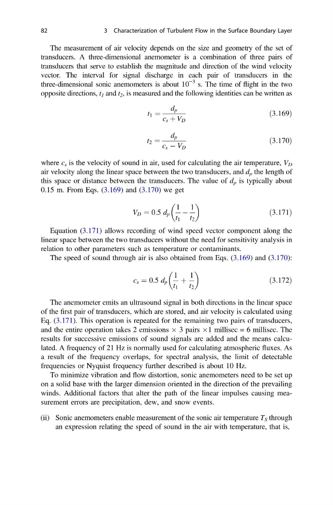
The measurement of air velocity depends on the size and geometry of the set of
transducers. A three-dimensional anemometer is a combination of three pairs of
transducers that serve to establish the magnitude and direction of the wind velocity
vector. The interval for signal discharge in each pair of transducers in the
three-dimensional sonic anemometers is about 10
−3 s. The time of flight in the two
opposite directions, t 1 and t 2 , is measured and the following identities can be written as
t 1 ¼
d p
c s þ V D
ð3:169Þ
t 2 ¼
d p
c s À V D
ð3:170Þ
where c s is the velocity of sound in air, used for calculating the air temperature, V D
air velocity along the linear space between the two transducers, and d p the length of
this space or distance between the transducers. The value of d p is typically about
0.15 m. From Eqs. (3.169) and (3.170) we get
V D ¼ 0:5 d p
1
t 1
À
1
t 2
ð3:171Þ
Equation (3.171) allows recording of wind speed vector component along the
linear space between the two transducers without the need for sensitivity analysis in
relation to other parameters such as temperature or contaminants.
The speed of sound through air is also obtained from Eqs. (3.169) and (3.170):
c s ¼ 0:5 d p
1
t 1
þ
1
t 2
ð3:172Þ
The anemometer emits an ultrasound signal in both directions in the linear space
of the first pair of transducers, which are stored, and air velocity is calculated using
Eq. (3.171). This operation is repeated for the remaining two pairs of transducers,
and the entire operation takes 2 emissions  3 pairs Â1 millisec = 6 millisec. The
results for successive emissions of sound signals are added and the means calculated. A frequency of 21 Hz is normally used for calculating atmospheric fluxes. As
a result of the frequency overlaps, for spectral analysis, the limit of detectable
frequencies or Nyquist frequency further described is about 10 Hz.
To minimize vibration and flow distortion, sonic anemometers need to be set up
on a solid base with the larger dimension oriented in the direction of the prevailing
winds. Additional factors that alter the path of the linear impulses causing measurement errors are precipitation, dew, and snow events.
(ii) Sonic anemometers enable measurement of the sonic air temperature T S through
an expression relating the speed of sound in the air with temperature, that is,
82
3 Characterization of Turbulent Flow in the Surface Boundary Layer
transducers. A three-dimensional anemometer is a combination of three pairs of
transducers that serve to establish the magnitude and direction of the wind velocity
vector. The interval for signal discharge in each pair of transducers in the
three-dimensional sonic anemometers is about 10
−3 s. The time of flight in the two
opposite directions, t 1 and t 2 , is measured and the following identities can be written as
t 1 ¼
d p
c s þ V D
ð3:169Þ
t 2 ¼
d p
c s À V D
ð3:170Þ
where c s is the velocity of sound in air, used for calculating the air temperature, V D
air velocity along the linear space between the two transducers, and d p the length of
this space or distance between the transducers. The value of d p is typically about
0.15 m. From Eqs. (3.169) and (3.170) we get
V D ¼ 0:5 d p
1
t 1
À
1
t 2
ð3:171Þ
Equation (3.171) allows recording of wind speed vector component along the
linear space between the two transducers without the need for sensitivity analysis in
relation to other parameters such as temperature or contaminants.
The speed of sound through air is also obtained from Eqs. (3.169) and (3.170):
c s ¼ 0:5 d p
1
t 1
þ
1
t 2
ð3:172Þ
The anemometer emits an ultrasound signal in both directions in the linear space
of the first pair of transducers, which are stored, and air velocity is calculated using
Eq. (3.171). This operation is repeated for the remaining two pairs of transducers,
and the entire operation takes 2 emissions  3 pairs Â1 millisec = 6 millisec. The
results for successive emissions of sound signals are added and the means calculated. A frequency of 21 Hz is normally used for calculating atmospheric fluxes. As
a result of the frequency overlaps, for spectral analysis, the limit of detectable
frequencies or Nyquist frequency further described is about 10 Hz.
To minimize vibration and flow distortion, sonic anemometers need to be set up
on a solid base with the larger dimension oriented in the direction of the prevailing
winds. Additional factors that alter the path of the linear impulses causing measurement errors are precipitation, dew, and snow events.
(ii) Sonic anemometers enable measurement of the sonic air temperature T S through
an expression relating the speed of sound in the air with temperature, that is,
82
3 Characterization of Turbulent Flow in the Surface Boundary Layer