

The complex or exponential form of a Fourier series 655
From equation (21),
e
j (ωt +α)
= cos(ωt + α) + j sin(ωt + α)
and
V m e
j (ωt +α)
= V m cos(ωt + α)
+ j V m sin(ωt + α)
Thus a sinusoidal varying voltage such as in equation (19) or equation (20) can be considered to be either
the real or the imaginary part of V m e j (ωt +α) , depending on whether the cosine or sine function is being
considered.
V m e j (ωt + α) may be rewritten as V m e j ωt e j α since
a m+n = a m × a n from the laws of indices, page 1.
The e j ωt term can be considered to arise from the fact
that a radius is rotated with an angular velocity ω, and
α is the angle at which the radius starts to rotate at time
t = 0 (see Chapter 14, page 143).
Thus, V m e j ωt e j α defines a phasor. In a particular circuit the angular velocity ω is the same for all the
elements thus the phasor can be adequately described
by V m ∠α, as suggested above.
Alternatively, if
v = V m cos(ωt + α) volts
and
cos θ =
1
2
e
j ϑ
+ e
− j θ
from equation (3), page 644
then
v = V m
1
2
e
j (ωt +α)
+ e
− j (ωt +α)
i.e.
v =
1
2
V m e
j ωt e
j α
+
1
2
V m e
− j ωt e
− j α
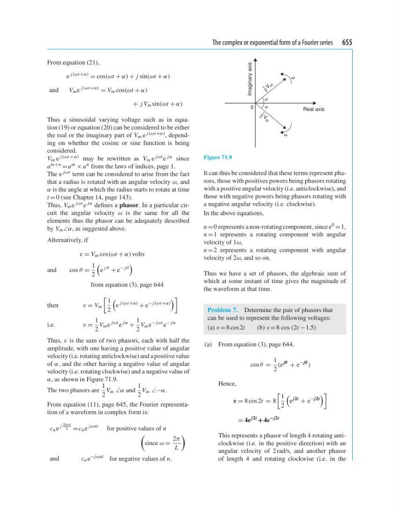
Thus, v is the sum of two phasors, each with half the
amplitude, with one having a positive value of angular
velocity (i.e. rotating anticlockwise) and a positive value
of α, and the other having a negative value of angular
velocity (i.e. rotating clockwise) and a negative value of
α, as shown in Figure 71.9.
The two phasors are
1
2
V m ∠α and
1
2
V m ∠−α.
From equation (11), page 645, the Fourier representation of a waveform in complex form is:
c n e
j 2πnt
L = c n e
j ωnt
for positive values of n
since ω =
2π
L
and
c n e
−j ωnt for negative values of n.
Real axis
Imaginary axis
␣
␣
0
1 V m
2
1
V
m
2
Figure 71.9
It can thus be considered that these terms represent phasors, those with positives powers being phasors rotating
with a positive angular velocity (i.e. anticlockwise), and
those with negative powers being phasors rotating with
a negative angular velocity (i.e. clockwise).
In the above equations,
n =0 represents a non-rotating component, since e
0
= 1,
n =1 represents a rotating component with angular
velocity of 1ω,
n =2 represents a rotating component with angular
velocity of 2ω, and so on.
Thus we have a set of phasors, the algebraic sum of
which at some instant of time gives the magnitude of
the waveform at that time.
Problem 7. Determine the pair of phasors that
can be used to represent the following voltages:
(a) v = 8 cos 2t
(b) v = 8 cos (2t − 1.5)
(a) From equation (3), page 644,
cos θ =
1
2
(e
jθ
+ e
−jθ
)
Hence,
v = 8 cos2t = 8
1
2
e
j2t
+ e
−j2t
= 4e
j2t
+ 4e
−j2t
This represents a phasor of length 4 rotating anticlockwise (i.e. in the positive direction) with an
angular velocity of 2 rad/s, and another phasor
of length 4 and rotating clockwise (i.e. in the