

174 Higher Engineering Mathematics
2
0
t (seconds)
v
p
i
p
i
v
1
2
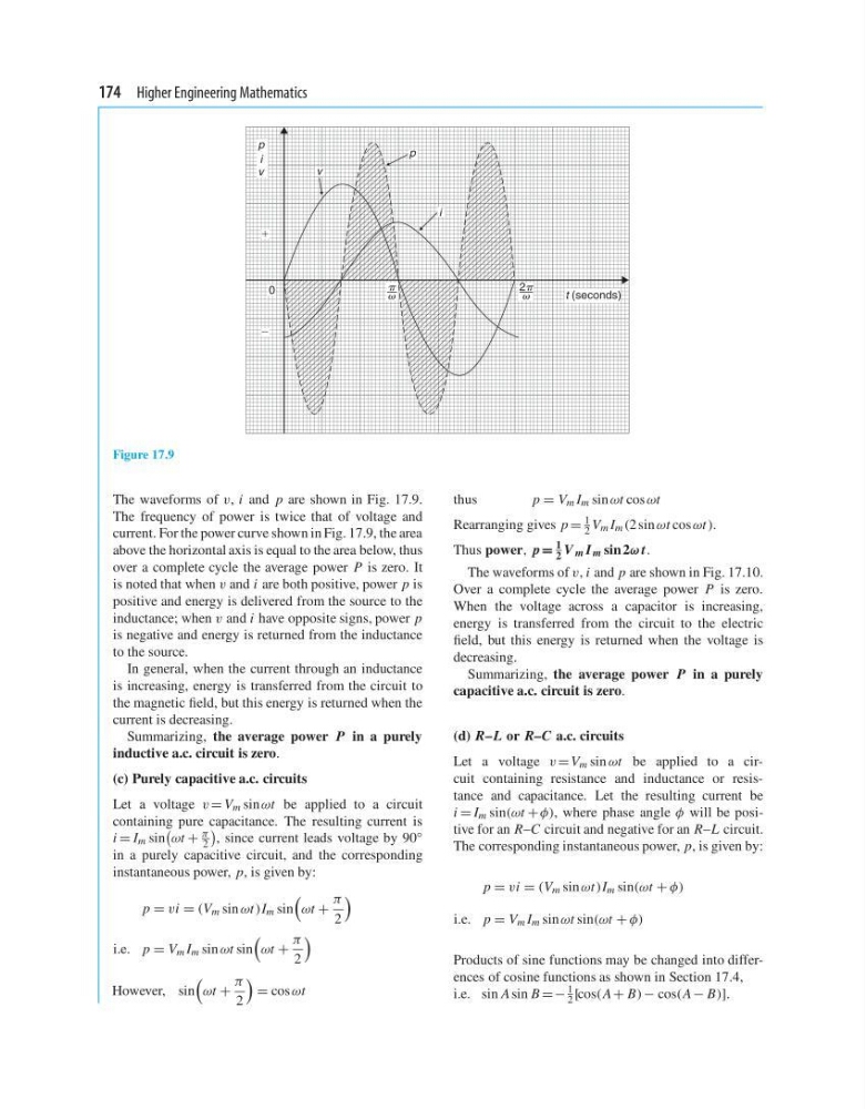
Figure 17.9
The waveforms of v, i and p are shown in Fig. 17.9.
The frequency of power is twice that of voltage and
current. For the power curve shown in Fig. 17.9, the area
above the horizontal axis is equal to the area below, thus
over a complete cycle the average power P is zero. It
is noted that when v and i are both positive, power p is
positive and energy is delivered from the source to the
inductance; when v and i have opposite signs, power p
is negative and energy is returned from the inductance
to the source.
In general, when the current through an inductance
is increasing, energy is transferred from the circuit to
the magnetic field, but this energy is returned when the
current is decreasing.
Summarizing, the average power P in a purely
inductive a.c. circuit is zero.
(c) Purely capacitive a.c. circuits
Let a voltage v = V m sin ωt be applied to a circuit
containing pure capacitance. The resulting current is
i = I m sin
ωt +
π
2
, since current leads voltage by 90 ◦
in a purely capacitive circuit, and the corresponding
instantaneous power, p, is given by:
p = vi = (V m sin ωt )I m sin
ωt +
π
2
i.e. p = V m I m sin ωt sin
ωt +
π
2
However, sin
ωt +
π
2
= cos ωt
thus
p = V m I m sin ωt cos ωt
Rearranging gives p =
1
2 V m I m (2 sin ωt cos ωt ).
Thus power, p =
1
2 V m I m sin 2ω t.
The waveforms of v, i and p are shown in Fig. 17.10.
Over a complete cycle the average power P is zero.
When the voltage across a capacitor is increasing,
energy is transferred from the circuit to the electric
field, but this energy is returned when the voltage is
decreasing.
Summarizing, the average power P in a purely
capacitive a.c. circuit is zero.
(d) R–L or R–C a.c. circuits
Let a voltage v = V m sin ωt be applied to a circuit containing resistance and inductance or resistance and capacitance. Let the resulting current be
i = I m sin(ωt + φ), where phase angle φ will be positive for an R–C circuit and negative for an R–L circuit.
The corresponding instantaneous power, p, is given by:
p = vi = (V m sin ωt )I m sin(ωt + φ)
i.e. p = V m I m sin ωt sin(ωt + φ)
Products of sine functions may be changed into differences of cosine functions as shown in Section 17.4,
i.e. sin A sin B =−
1
2 [cos(A + B) − cos(A − B)].
2
0
t (seconds)
v
p
i
p
i
v
1
2
Figure 17.9
The waveforms of v, i and p are shown in Fig. 17.9.
The frequency of power is twice that of voltage and
current. For the power curve shown in Fig. 17.9, the area
above the horizontal axis is equal to the area below, thus
over a complete cycle the average power P is zero. It
is noted that when v and i are both positive, power p is
positive and energy is delivered from the source to the
inductance; when v and i have opposite signs, power p
is negative and energy is returned from the inductance
to the source.
In general, when the current through an inductance
is increasing, energy is transferred from the circuit to
the magnetic field, but this energy is returned when the
current is decreasing.
Summarizing, the average power P in a purely
inductive a.c. circuit is zero.
(c) Purely capacitive a.c. circuits
Let a voltage v = V m sin ωt be applied to a circuit
containing pure capacitance. The resulting current is
i = I m sin
ωt +
π
2
, since current leads voltage by 90 ◦
in a purely capacitive circuit, and the corresponding
instantaneous power, p, is given by:
p = vi = (V m sin ωt )I m sin
ωt +
π
2
i.e. p = V m I m sin ωt sin
ωt +
π
2
However, sin
ωt +
π
2
= cos ωt
thus
p = V m I m sin ωt cos ωt
Rearranging gives p =
1
2 V m I m (2 sin ωt cos ωt ).
Thus power, p =
1
2 V m I m sin 2ω t.
The waveforms of v, i and p are shown in Fig. 17.10.
Over a complete cycle the average power P is zero.
When the voltage across a capacitor is increasing,
energy is transferred from the circuit to the electric
field, but this energy is returned when the voltage is
decreasing.
Summarizing, the average power P in a purely
capacitive a.c. circuit is zero.
(d) R–L or R–C a.c. circuits
Let a voltage v = V m sin ωt be applied to a circuit containing resistance and inductance or resistance and capacitance. Let the resulting current be
i = I m sin(ωt + φ), where phase angle φ will be positive for an R–C circuit and negative for an R–L circuit.
The corresponding instantaneous power, p, is given by:
p = vi = (V m sin ωt )I m sin(ωt + φ)
i.e. p = V m I m sin ωt sin(ωt + φ)
Products of sine functions may be changed into differences of cosine functions as shown in Section 17.4,
i.e. sin A sin B =−
1
2 [cos(A + B) − cos(A − B)].