

52
D. Tomaszewicz et al.
The modification of frictional contact mentioned above allows including
the anchor thread in numerical calculations. This is the feature introduced in
ANSYS 15.0. It allows to define a threaded connection between cylindrical surfaces
without modelling the exact thread geometry. The most important data is necessary
to provide: a mean pitch diameter, a pitch distance and a thread angle. Based on these
values, the program modifies a computational model by simulating a real threaded
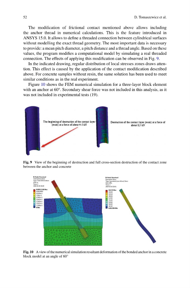
connection. The effects of applying this modification can be observed in Fig. 9.
In the indicated drawing, regular distribution of local stresses zones draws attention. This effect is caused by the application of the contact modification described
above. For concrete samples without resin, the same solution has been used to meet
similar conditions as in the real experiment.
Figure 10 shows the FEM numerical simulation for a three-layer block element
with an anchor at 60°. Secondary shear force was not included in this analysis, as it
was not included in experimental tests (19).
Fig. 9 View of the beginning of destruction and full cross-section destruction of the contact zone
between the anchor and concrete
Fig. 10 A view of the numerical simulation resultant deformation of the bonded anchor in a concrete
block model at an angle of 60°
D. Tomaszewicz et al.
The modification of frictional contact mentioned above allows including
the anchor thread in numerical calculations. This is the feature introduced in
ANSYS 15.0. It allows to define a threaded connection between cylindrical surfaces
without modelling the exact thread geometry. The most important data is necessary
to provide: a mean pitch diameter, a pitch distance and a thread angle. Based on these
values, the program modifies a computational model by simulating a real threaded
connection. The effects of applying this modification can be observed in Fig. 9.
In the indicated drawing, regular distribution of local stresses zones draws attention. This effect is caused by the application of the contact modification described
above. For concrete samples without resin, the same solution has been used to meet
similar conditions as in the real experiment.
Figure 10 shows the FEM numerical simulation for a three-layer block element
with an anchor at 60°. Secondary shear force was not included in this analysis, as it
was not included in experimental tests (19).
Fig. 9 View of the beginning of destruction and full cross-section destruction of the contact zone
between the anchor and concrete
Fig. 10 A view of the numerical simulation resultant deformation of the bonded anchor in a concrete
block model at an angle of 60°