

Pull-Out Tests and Numerical Simulations …
49
42.5
42.5
20
6 0
Vertical force
- pull-out
fastening M 20 to
the beam
frame - 2 flat
at a distance
of 10 cm in
the light
angle to stabilize
the sample
screw M 20
screw M 8
DETAIL A
gratings
- flat
bars
cylinder
A
45°
BALANCE OF FORCE
ANGLE 45°
VERTICAL FORCE
HORIZONTAL FORCE
ANCHOR LOCATION RELATIVE TO THE
SAMPLE
stend beam
steel rope
O10mm
hook
with ear
eyelet screwed
into the cylinder
rope clamp O10mm
eyelet with thread M12
steel anchor O12mm
screw M 20
concrete
sample with
insulation
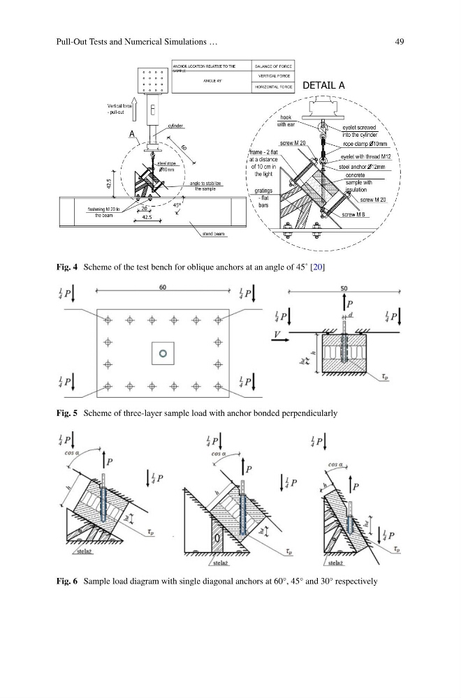
Fig. 4 Scheme of the test bench for oblique anchors at an angle of 45˚ [20]
Fig. 5 Scheme of three-layer sample load with anchor bonded perpendicularly
Fig. 6 Sample load diagram with single diagonal anchors at 60°, 45° and 30° respectively
49
42.5
42.5
20
6 0
Vertical force
- pull-out
fastening M 20 to
the beam
frame - 2 flat
at a distance
of 10 cm in
the light
angle to stabilize
the sample
screw M 20
screw M 8
DETAIL A
gratings
- flat
bars
cylinder
A
45°
BALANCE OF FORCE
ANGLE 45°
VERTICAL FORCE
HORIZONTAL FORCE
ANCHOR LOCATION RELATIVE TO THE
SAMPLE
stend beam
steel rope
O10mm
hook
with ear
eyelet screwed
into the cylinder
rope clamp O10mm
eyelet with thread M12
steel anchor O12mm
screw M 20
concrete
sample with
insulation
Fig. 4 Scheme of the test bench for oblique anchors at an angle of 45˚ [20]
Fig. 5 Scheme of three-layer sample load with anchor bonded perpendicularly
Fig. 6 Sample load diagram with single diagonal anchors at 60°, 45° and 30° respectively