

48
D. Tomaszewicz et al.
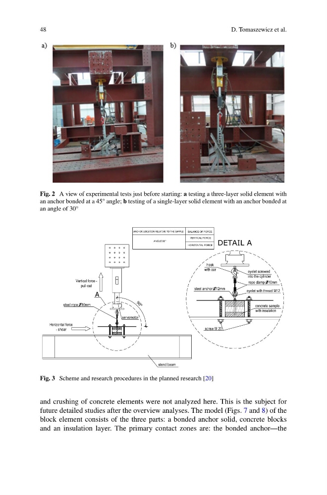
Fig. 2 A view of experimental tests just before starting: a testing a three-layer solid element with
an anchor bonded at a 45° angle; b testing of a single-layer solid element with an anchor bonded at
an angle of 30°
Vertical force -
pull-out
Horizontal force
- shear
stend beam
A
steel rope O10mm
concrete sample
with insulation
screw M 20
hook
with ear
eyelet with thread M12
eyelet screwed
into the cylinder
steel anchor O12mm
rope clamp O10mm
servomotor
9
0
°
BALANCE OF FORCE
ANGLE 90°
VERTICAL FORCE
HORIZONTAL FORCE
DETAIL A
ANCHOR LOCATION RELATIVE TO THE SAMPLE
Fig. 3 Scheme and research procedures in the planned research [20]
and crushing of concrete elements were not analyzed here. This is the subject for
future detailed studies after the overview analyses. The model (Figs. 7 and 8) of the
block element consists of the three parts: a bonded anchor solid, concrete blocks
and an insulation layer. The primary contact zones are: the bonded anchor—the
D. Tomaszewicz et al.
Fig. 2 A view of experimental tests just before starting: a testing a three-layer solid element with
an anchor bonded at a 45° angle; b testing of a single-layer solid element with an anchor bonded at
an angle of 30°
Vertical force -
pull-out
Horizontal force
- shear
stend beam
A
steel rope O10mm
concrete sample
with insulation
screw M 20
hook
with ear
eyelet with thread M12
eyelet screwed
into the cylinder
steel anchor O12mm
rope clamp O10mm
servomotor
9
0
°
BALANCE OF FORCE
ANGLE 90°
VERTICAL FORCE
HORIZONTAL FORCE
DETAIL A
ANCHOR LOCATION RELATIVE TO THE SAMPLE
Fig. 3 Scheme and research procedures in the planned research [20]
and crushing of concrete elements were not analyzed here. This is the subject for
future detailed studies after the overview analyses. The model (Figs. 7 and 8) of the
block element consists of the three parts: a bonded anchor solid, concrete blocks
and an insulation layer. The primary contact zones are: the bonded anchor—the