

Analog and Digital Filters
573
R.6.54 Practical fi lters often used in applications (appliances) are named after the researchers, often mathematicians who studied the polynomials that make up the transfer
function that best matches the ideal fi lter characteristics.
The most common practical fi lters are referred to as
a. Butterworth
b. Chebyshev
c. Cauer (elliptic)
d. Bessel
These fi lters return characteristics based on the facts that the system transfer
function presents regions with smooth or ripple (oscillations) behavior.
R.6.55 The Butterworth fi lter is probably the most popular practical fi lter. The fi lter characteristics consist of maximum fl at response in the pass-band region, with no ripples either in the pass band or stop band.
The basic design approach consists of choosing an appropriate model of the
transfer function H(jw). From this transfer function, the complex conjugate H(−jw)
is then obtained, and from the product H(jw) * H(−jw) = ͉H(jw)
2
͉ the poles of the
transfer function can be evaluated.
The Butterworth magnitude-squared response of an n-order LPF is given by the
following equation:
H(jw) * H( jw) H (jw)
a
Ϫ
ϩ
ϭ
ϭ
"
"
2
1
1
2
w
w p
n
(The subindex a in H stands for analog.)
The normalized Butterworth magnitude is given by
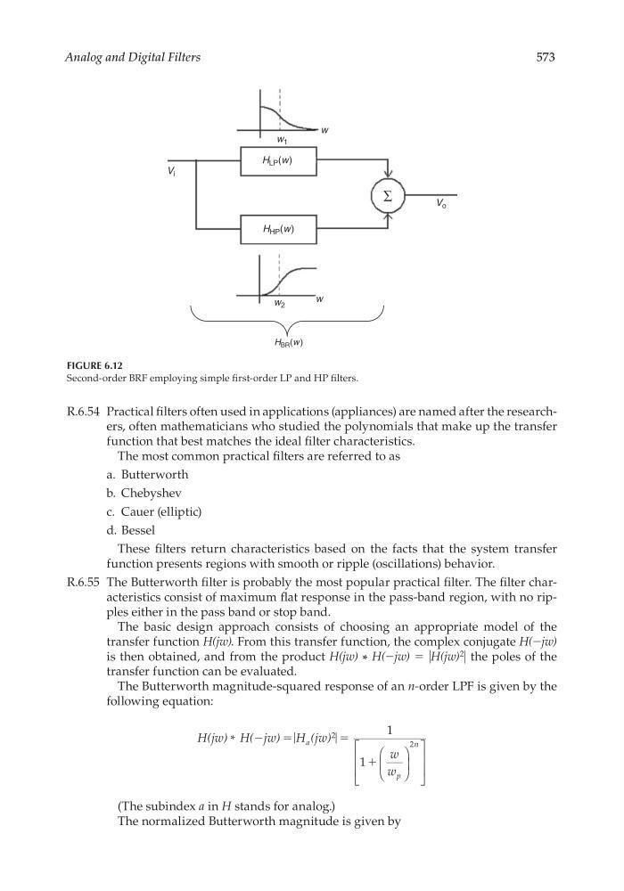
FIGURE 6.12
Second-order BRF employing simple fi rst-order LP and HP fi lters.
H LP (w)
H HP (w)
H BR (w )
V i
V o
w 1
w 2
w
w
∑
CRC_47760_CH006.indd 573
CRC_47760_CH006.indd 573
7/23/2008 2:26:33 PM
7/23/2008 2:26:33 PM