

440
Practical MATLAB
® Applications for Engineers
4. Use MATLAB and obtain expressions for I 1 (s) and I 2 (s)
5. Use MATLAB to evaluate the initial- and fi nal value of each loop current by applying the initial and fi nal value theorems
6. Use MATLAB to obtain solutions for i 1 (t) and i 2 (t), for t ≥ 0
7. Use MATLAB to obtain plots of i 1 (t) versus t and i 2 (t) versus t, for t ≥ 0
8. Discuss the results obtained
The MATLAB solution is given as follows by the script fi le loop_diffeqs:
ANALYTICAL Solution
Part 1
The loop equations in the time domain for t ≥ 0 are
100
20
10
0
10
20
1
1
2
1
2
2
u t
di t
dt
i t
i t
i t
i t
di t
d
( )
( )
( )
( )
( )
( )
( )
ϭ
ϩ
ϭ
ϩ
ϩ
Ϫ
Ϫ
t t
Part 2
The loop equations in the frequency domain are
100
20
10
0
10
20
1
2
1
2
s
s
I s
I s
I s
s
I s
ϭ ϩ
ϭ
ϩ ϩ
(
) ( )
( )
( ) (
) ( )
Ϫ
Ϫ
Part 3
The matrix loop equation of the network in the frequency domain is given by
100
0
20
10
10
20
1
2
ր
Ϫ
Ϫ
s
s
s
I s
I s
ϭ
ϩ
ϩ
( )
( )
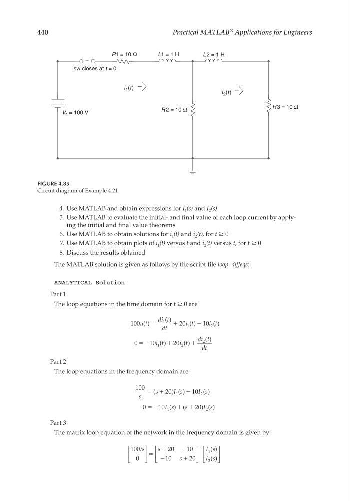
V 1 = 100 V
R1 = 10 Ω
L1 = 1 H
i 1 (t )
i 2 (t )
sw closes at t = 0
L 2 = 1 H
R 2 = 10 Ω
R 3 = 10 Ω
FIGURE 4.85
Circuit diagram of Example 4.21.
CRC_47760_CH004.indd 440
CRC_47760_CH004.indd 440
7/28/2008 12:26:22 PM
7/28/2008 12:26:22 PM
Practical MATLAB
® Applications for Engineers
4. Use MATLAB and obtain expressions for I 1 (s) and I 2 (s)
5. Use MATLAB to evaluate the initial- and fi nal value of each loop current by applying the initial and fi nal value theorems
6. Use MATLAB to obtain solutions for i 1 (t) and i 2 (t), for t ≥ 0
7. Use MATLAB to obtain plots of i 1 (t) versus t and i 2 (t) versus t, for t ≥ 0
8. Discuss the results obtained
The MATLAB solution is given as follows by the script fi le loop_diffeqs:
ANALYTICAL Solution
Part 1
The loop equations in the time domain for t ≥ 0 are
100
20
10
0
10
20
1
1
2
1
2
2
u t
di t
dt
i t
i t
i t
i t
di t
d
( )
( )
( )
( )
( )
( )
( )
ϭ
ϩ
ϭ
ϩ
ϩ
Ϫ
Ϫ
t t
Part 2
The loop equations in the frequency domain are
100
20
10
0
10
20
1
2
1
2
s
s
I s
I s
I s
s
I s
ϭ ϩ
ϭ
ϩ ϩ
(
) ( )
( )
( ) (
) ( )
Ϫ
Ϫ
Part 3
The matrix loop equation of the network in the frequency domain is given by
100
0
20
10
10
20
1
2
ր
Ϫ
Ϫ
s
s
s
I s
I s
ϭ
ϩ
ϩ
( )
( )
V 1 = 100 V
R1 = 10 Ω
L1 = 1 H
i 1 (t )
i 2 (t )
sw closes at t = 0
L 2 = 1 H
R 2 = 10 Ω
R 3 = 10 Ω
FIGURE 4.85
Circuit diagram of Example 4.21.
CRC_47760_CH004.indd 440
CRC_47760_CH004.indd 440
7/28/2008 12:26:22 PM
7/28/2008 12:26:22 PM