

Fourier and Laplace
439
−4
−4
−2
−6
−2
0
2
4
6
complex frequency s
14
12
10
8
6
4
2
0
V1 (s)
V1 (s) versus s
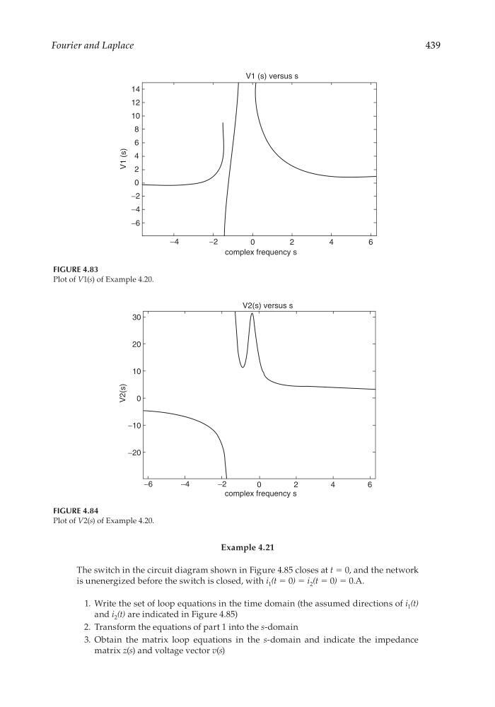
FIGURE 4.83
Plot of V1(s) of Example 4.20.
−6
−20
−10
−4
−2
0
0
10
20
30
complex frequency s
2
4
6
V2(s)
V2(s) versus s
FIGURE 4.84
Plot of V2(s) of Example 4.20.
Example 4.21
The switch in the circuit diagram shown in Figure 4.85 closes at t = 0, and the network
is unenergized before the switch is closed, with i 1 (t = 0) = i 2 (t = 0) = 0.A.
1. Write the set of loop equations in the time domain (the assumed directions of i 1 (t)
and i 2 (t) are indicated in Figure 4.85)
2. Transform the equations of part 1 into the s-domain
3. Obtain the matrix loop equations in the s-domain and indicate the impedance
matrix z(s) and voltage vector v(s)
CRC_47760_CH004.indd 439
CRC_47760_CH004.indd 439
7/28/2008 12:26:21 PM
7/28/2008 12:26:21 PM
439
−4
−4
−2
−6
−2
0
2
4
6
complex frequency s
14
12
10
8
6
4
2
0
V1 (s)
V1 (s) versus s
FIGURE 4.83
Plot of V1(s) of Example 4.20.
−6
−20
−10
−4
−2
0
0
10
20
30
complex frequency s
2
4
6
V2(s)
V2(s) versus s
FIGURE 4.84
Plot of V2(s) of Example 4.20.
Example 4.21
The switch in the circuit diagram shown in Figure 4.85 closes at t = 0, and the network
is unenergized before the switch is closed, with i 1 (t = 0) = i 2 (t = 0) = 0.A.
1. Write the set of loop equations in the time domain (the assumed directions of i 1 (t)
and i 2 (t) are indicated in Figure 4.85)
2. Transform the equations of part 1 into the s-domain
3. Obtain the matrix loop equations in the s-domain and indicate the impedance
matrix z(s) and voltage vector v(s)
CRC_47760_CH004.indd 439
CRC_47760_CH004.indd 439
7/28/2008 12:26:21 PM
7/28/2008 12:26:21 PM